
This step describes in the installation of the RTD video board & Arduino etc, and the remaining wiring required.

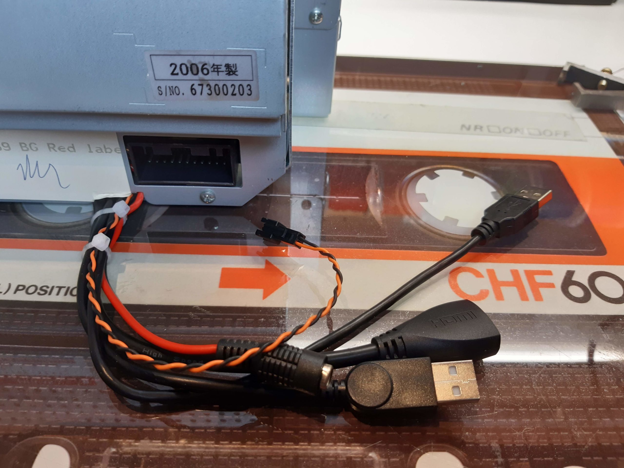
Plug in an 30cm HDMI right angle extension cable to the RTD board, and a Micro USB right angle extension to the Arduino.
On the TV version of the modification these boards are the opposite way round, so you would use the opposite direction right-angle versions of these extension cables
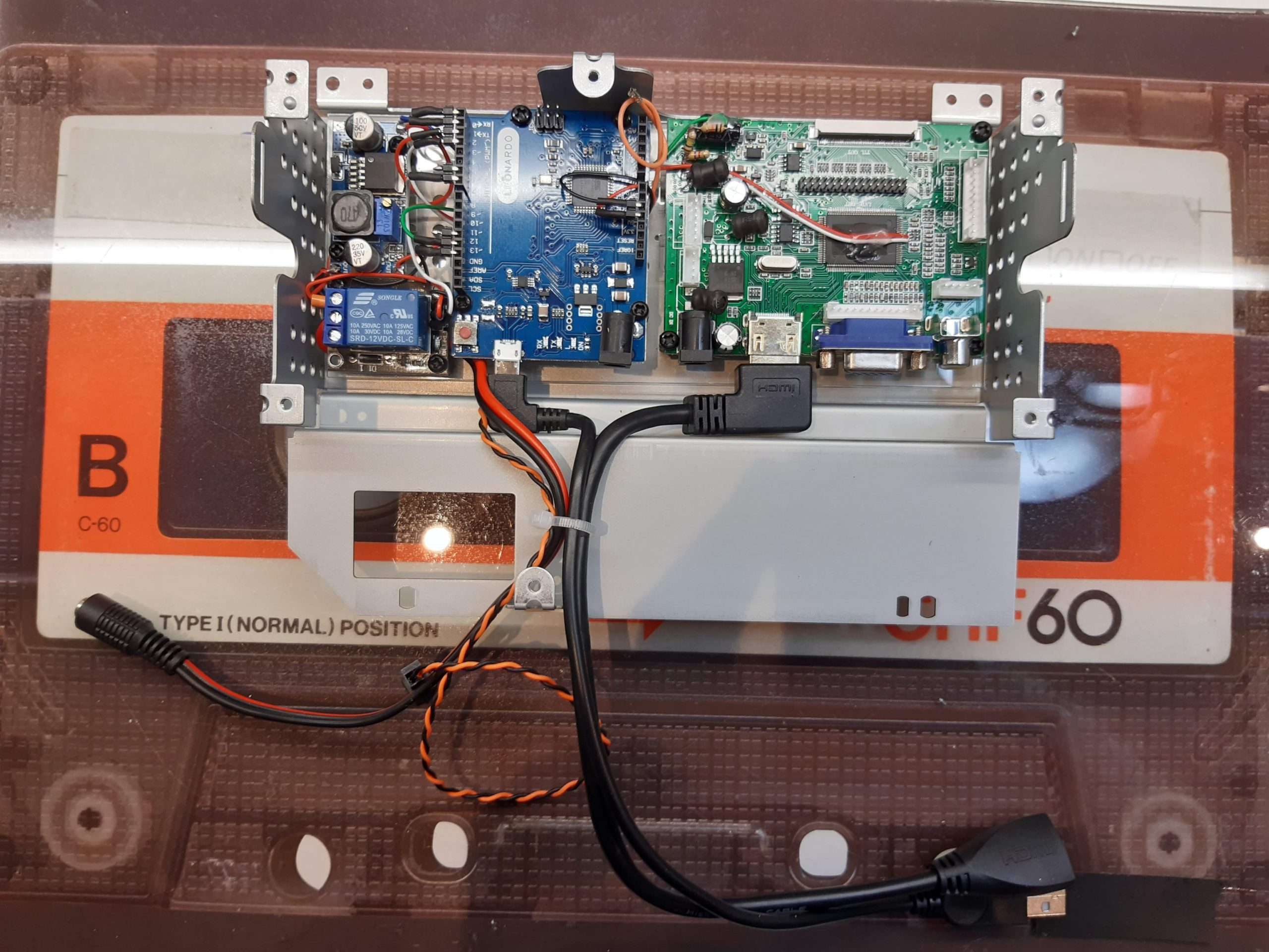
Install the control board assembly inside the touchscreen backplate and secure with M3 nylon nuts on the rear. Guide the cables either side of the metal tag and secure with a cable tie.

You can snip off the excess thread on the screws with wire cutters.

Bring in the original control board and lean it up so that the new connectors are accessible and it’s in a position where it can later be mounted back in it’s original position.
Add the Orange (ACC) wire from the opto assembly into the 4-pin molex connector and plug into the RTD board
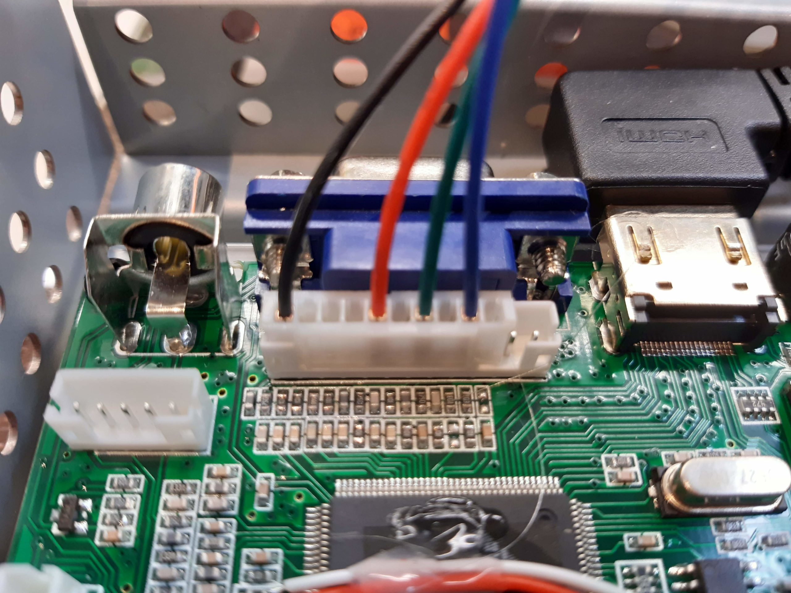
Temporarily plug in the 10-pin molex connector. This will be removed later as the White (Sync ) wire will have to be added to the plug when the board is re-installed
Note that the the connector should be plugged in as shown so that the 2 spare pins are nearest the middle of the board
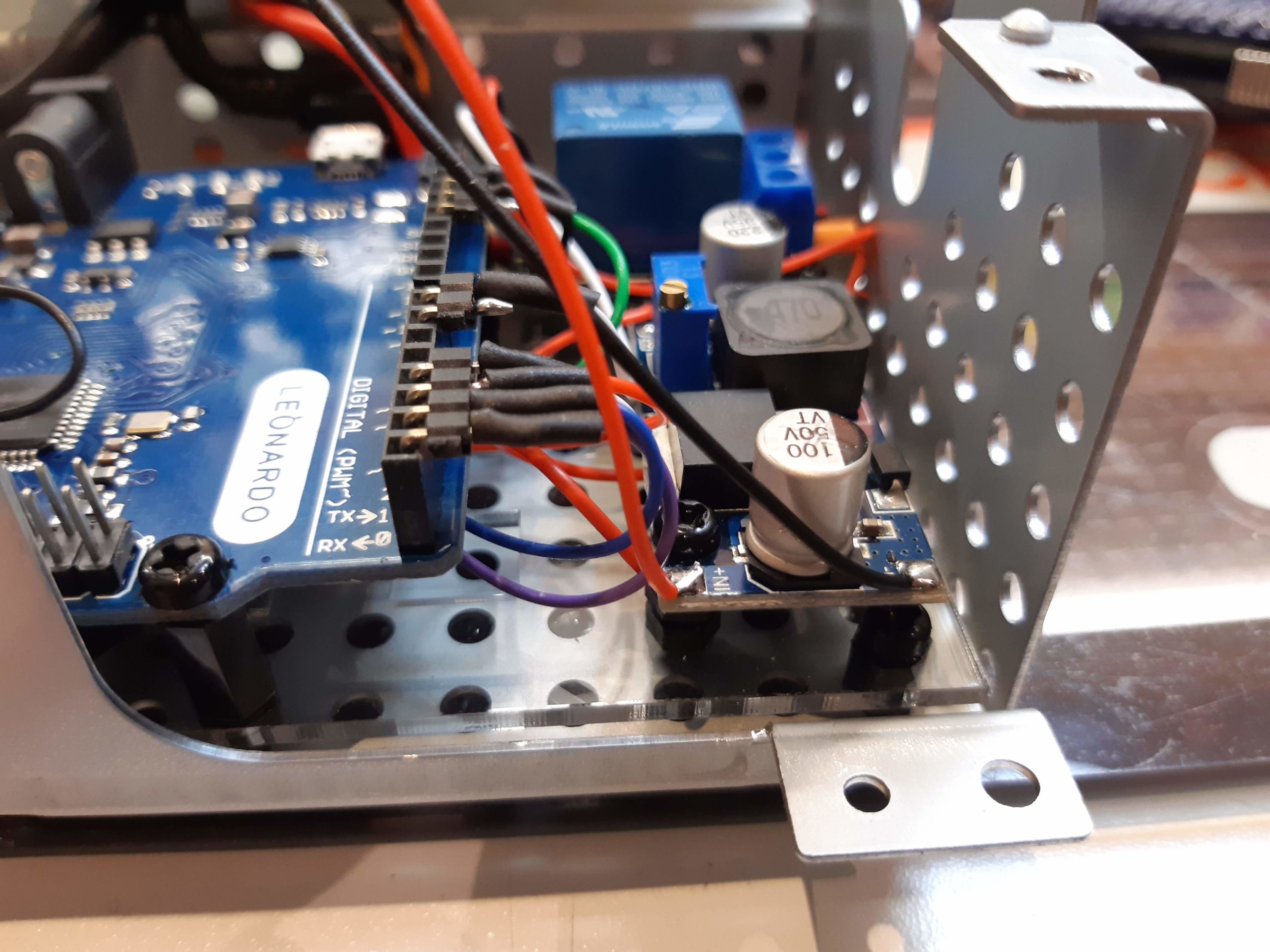
Solder the Red and Black (+12v and Ground) wires to the LM3946 voltage regulator.
REMINDER: Don’t forget to ensure that this was previously set for a +5v output – otherwise your Arduino will be fried at power-on!

Solder a 250mm blue wire to pin 29 of CN1 on the original board. This is the PWM signal for the screen brightness used to detect the brightness setting in the Jaguar menu. Secure with dot of hot-melt glue.

Solder this to pin 12 of the Arduino. You can see the green wire on Pin 13 that is the PWM out that goes to the RTD board.

Solder the Grey wire coming from the touchscreen control relay to pin 6 on the Arduino.

Now bring the original control board towards its final position and plug in the 2 x 4 pin connectors from the touch matrix connections.
Black – A2
Brown – A3
Red – A4
Orange – A5
Yellow – D8
Green – D9
Blue – D10
Purple – D11
Secure all pin headers with hot-melt glue.

Mount the original board along with the plastic insulating panel back on its mountings and secure with screws.

Reassemble the back panel, feeding the new wiring through the gap at the bottom. Pay attention to the routing of the USB touchscreen cable, which has to come around the side of the board rather than below, to prevent being pinched when the panel is screwed down.

Ensure none of the cables are trapped when screwing the panel back down.
And secure the bundle with 2 cable ties.

Unplug the 10-pin molex connector from the RTD board and add the White Sync) wire as shown, and plug back into the RTD board.
Re-connect the original plugs with Brown and White wires, and the original ribbon cable going to CN1
Continue to LCD panel and touchscreen