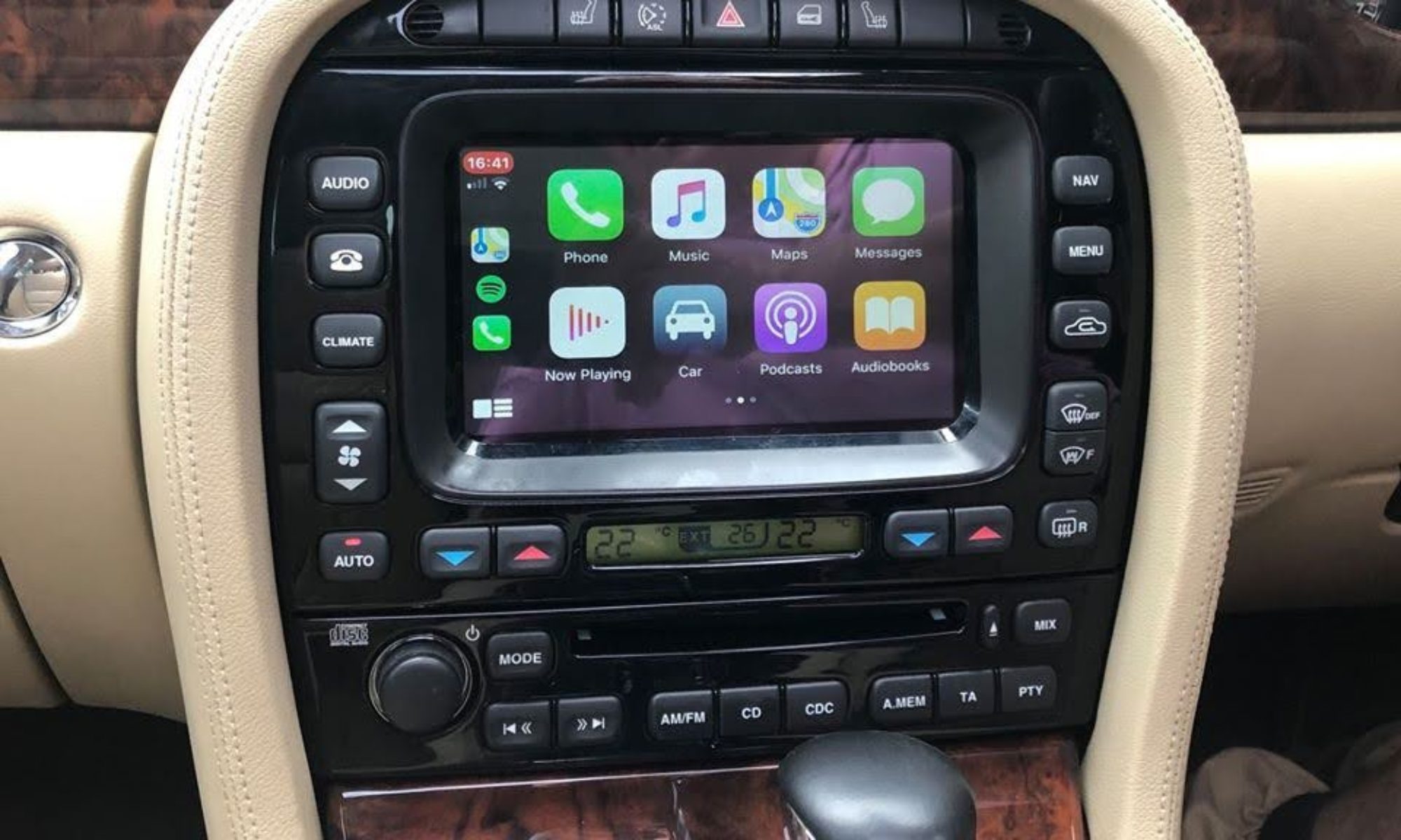

There is no built-in facility to get external audio into the Jaguar CD Player, so it needs some internal modification to add an aux-in. This is required to get audio from the Odroid into the Jag audio system, which will allow you to stream audio via Bluetooth from your phone or use the Android media player to play MP3s from a USB stick, or stream audio via Spotify, get voice Navigation instructions etc etc.
This Advanced version of the aux-in modification will also allow you to use the steering wheel controls as well as use the front panel buttons to skip track forwards and backwards when connected to an Odroid or other car computer, and pressing CD will pause/play in the same way as it does when playing a CD. You can switch between the internal CD Audio and the Aux-in by pressing the A.MEM button on the head unit.
You can also do this bit as a stand alone mod without the complete head unit conversion if you just want to be able to plug in your phone/MP3 player to play tunes (but see the warning below about Analogue vs Digital transport).
If you have the Cassette or MiniDisc player just get a used CD player, they’re a drop-in replacement with no configuration required.
IMPORTANT NOTE! – if your car is equipped with Premium Audio (i.e. has Alpine badges on the front door speakers, subwoofer and an external amplifier using the D2B bus) then the CD player utilises an Analogue L/R line level audio signal internally. If your car has no external amplifier (i.e. the speakers are directly connected to the CD player’s internal amplifier) then a Digital SPDIF internal signal is used. This means you cannot directly connect a phone/ipod etc into a unit with Standard audio without an Analogue to Digital converter.
Follow the relevant instructions below depending on how your car is equipped – most of the information is applicable to both types of audio system, but follow the specific instructions marked PREMIUM AUDIO EQUIPPED CARS if you have the Premium Alpine audio with separate amplifier, or STANDARD AUDIO EQUIPPED CARS if you don’t:
Below is the wiring diagram showing how everything connects to the internals of the CD player. You will require the following components:
NOTE: the links are examples only and not necessarily a recommendation of the supplier. You might be able to find the same component elsewhere cheaper
- Arduino Pro Micro
- DPDT 12v coil relay e.g. Omron G5V-2 12DC
- 1N4001 or equivalent diode
- 10k 1/4w resistor
- 4 x 1M 1/4w resistor
- BC337 or equivalent NPN transistor
- 200mm right angle micro-usb cable
- 180mm lengths of 7/0.2mm equipment hookup wire, various colours
- Twin Phono plug to Phono socket lead
- Heatshrink 19.1mm diameter/30mm flat
- Cable ties 2.5mm x 100mm


We’ll be using an S-Type unit for this guide, but the X-Type and XJ X350/8 are the same other than slight differences in the front bezel plastic moulding.
Before we open up the player we need to prepare the Arduino micro-controller that will scan all the buttons and control the switching of the relay.
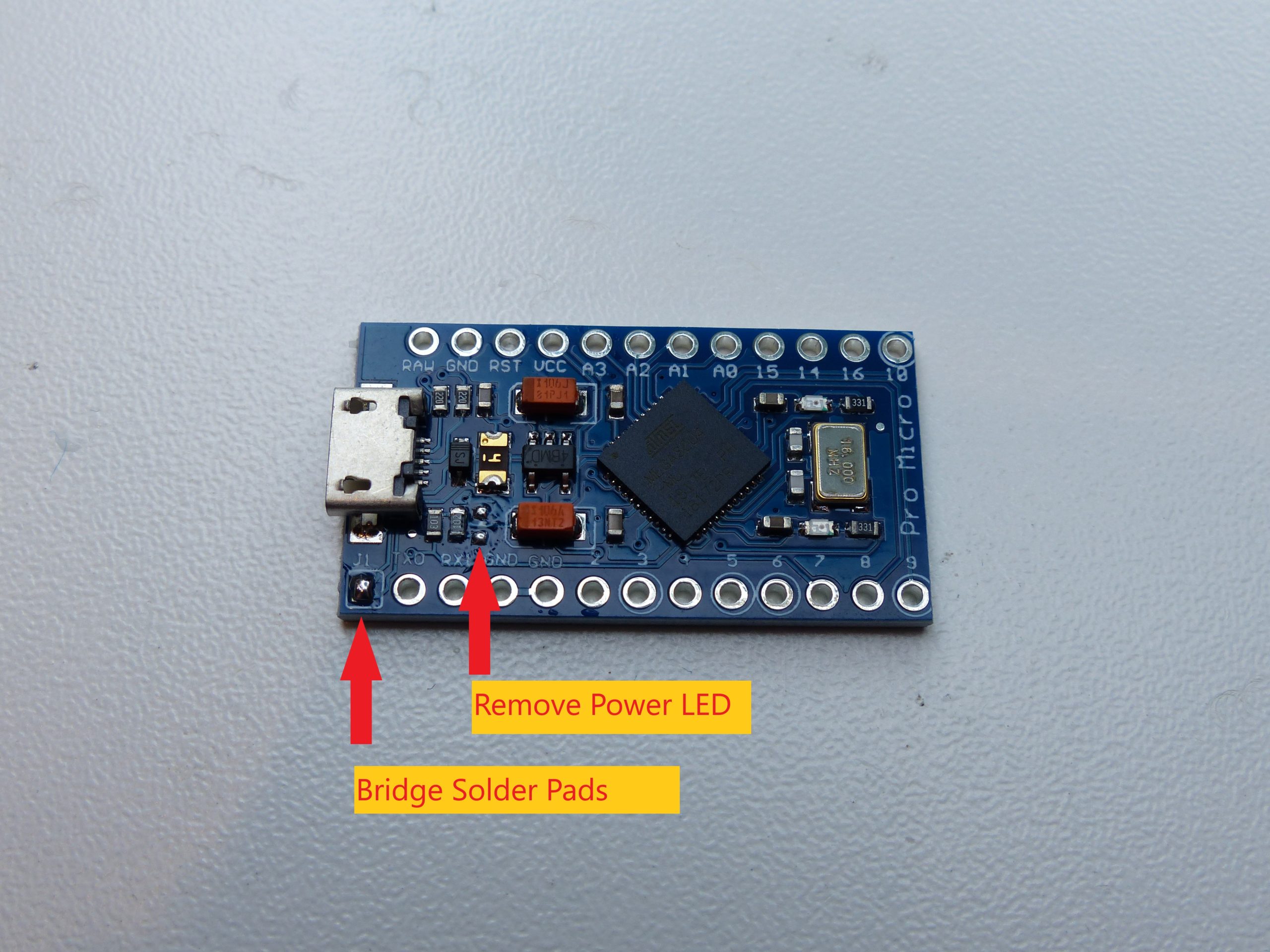
You need an Arduino Pro-Micro, the 5v 16Mhz version. This has a micro-USB socket mounted on it and shouldn’t be confused with other similar Arduinos that have mini-usb or no connector on them.
The Arduino needs some modifications before it can be used. Remove the power LED, and bridge the solder pads J1.

In order to program the Arduino with the software (known as a sketch) that will control the CD player aux-in switching, first connect the Arduino to your computer via the 20cm micro-usb cable.

Download the latest sketch version here and load it into the Arduino IDE:
JagDroid CD Player Control V2.41
Look for the line that says:
//#debug
and delete the two slashes. This enables debug mode that we will need later.
Load this sketch into the Arduino IDE, and program into the Arduino micro.

Now we can move on to soldering all the wires to the Arduino Pro Micro. All wires on the bottom row should be approximately 180mm in length. On the top row the red is 120mm, Blue and Purple 220mm, and Brown is 160mm.
- VCC – Red
- A2 – Purple
- A3 – Blue
- D15 – Brown
- GND – Black
- D2 – Orange
- D3 – Brown
- D4 – Grey
- D5 – White
- D6 – Blue
- D7 – Green
- D8 – Yellow
- D9 – Purple

On the rear side, solder the 4 x 1MOhm pulldown resistors to D6 thru D9, with the common side connected to 0v.
Then separate the 9 wires D2-D9 & 0v as shown.
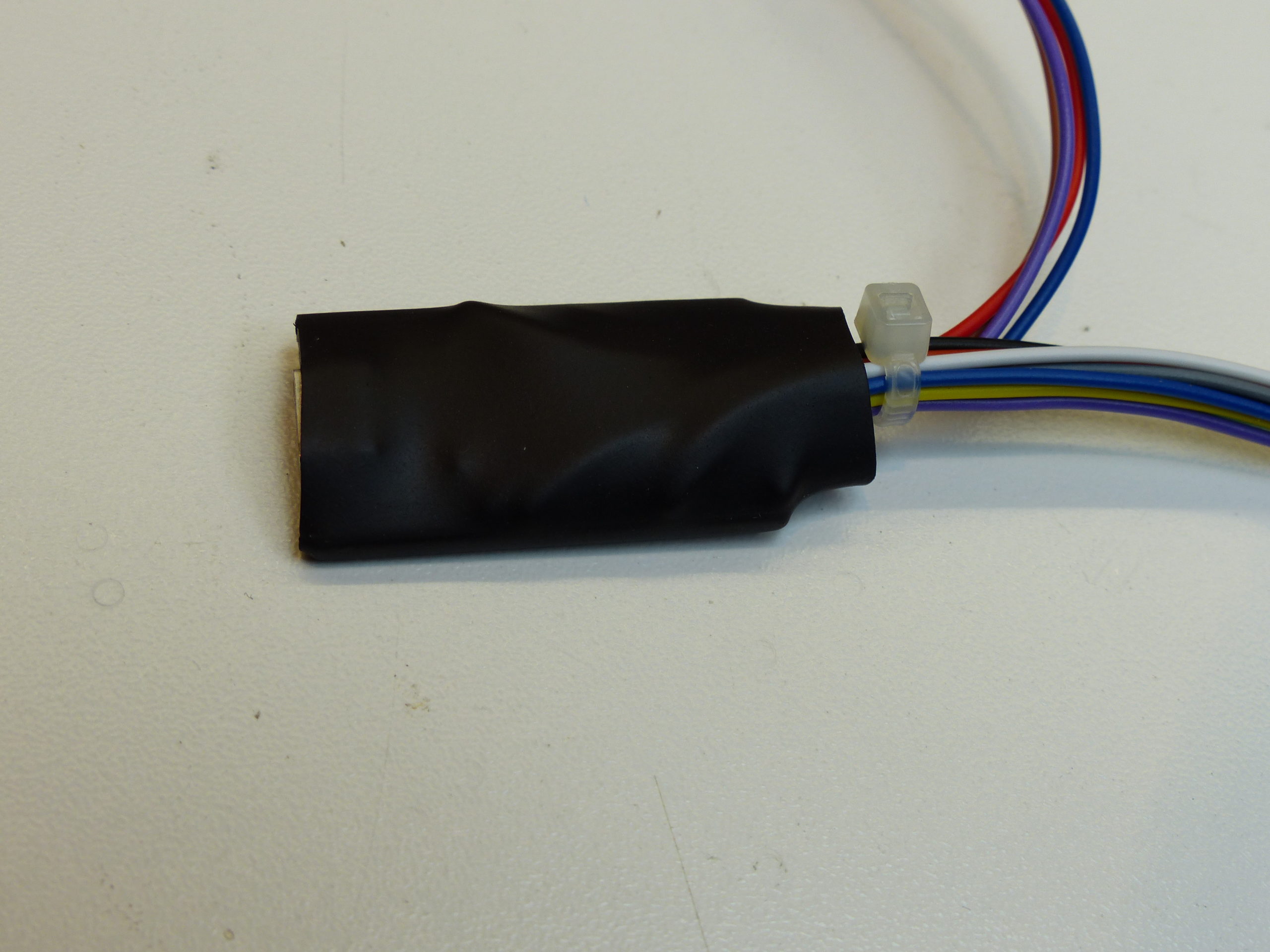
Use some heatshrink to cover the Arduino, or alternatively some PVC tape will do.

Remove the three screws on the back of the CD player and prise off the top metal lid.
The CD transport mechanism is held in place by 4 screws – remove the screws and lift the transport out and disconnect the ribbon cable connecting it to the main board.

Remove the 2 screws either side of the front plastic bezel
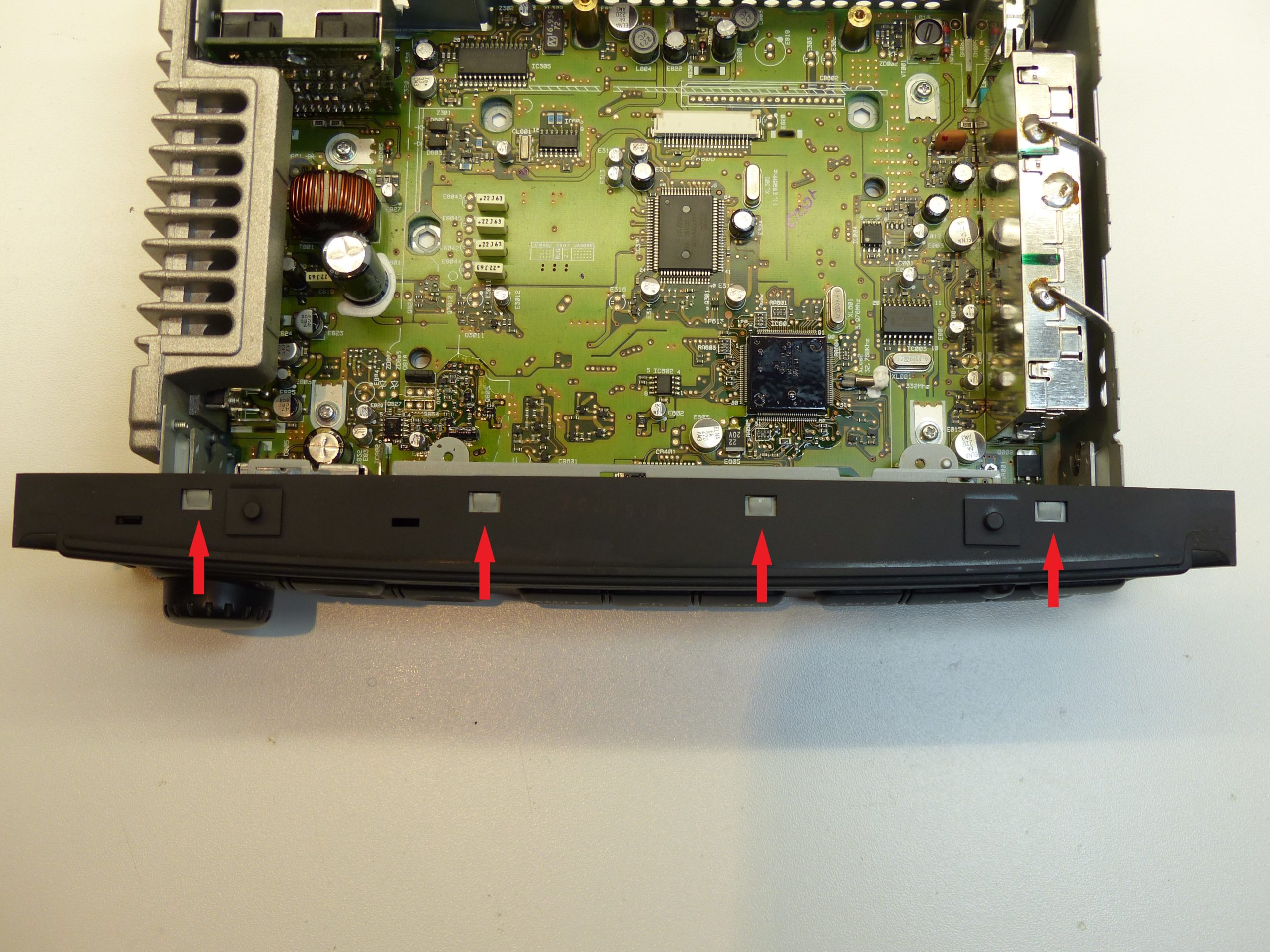
Gently prise the top of the bezel away from the metal clips using a flat bladed screwdriver.
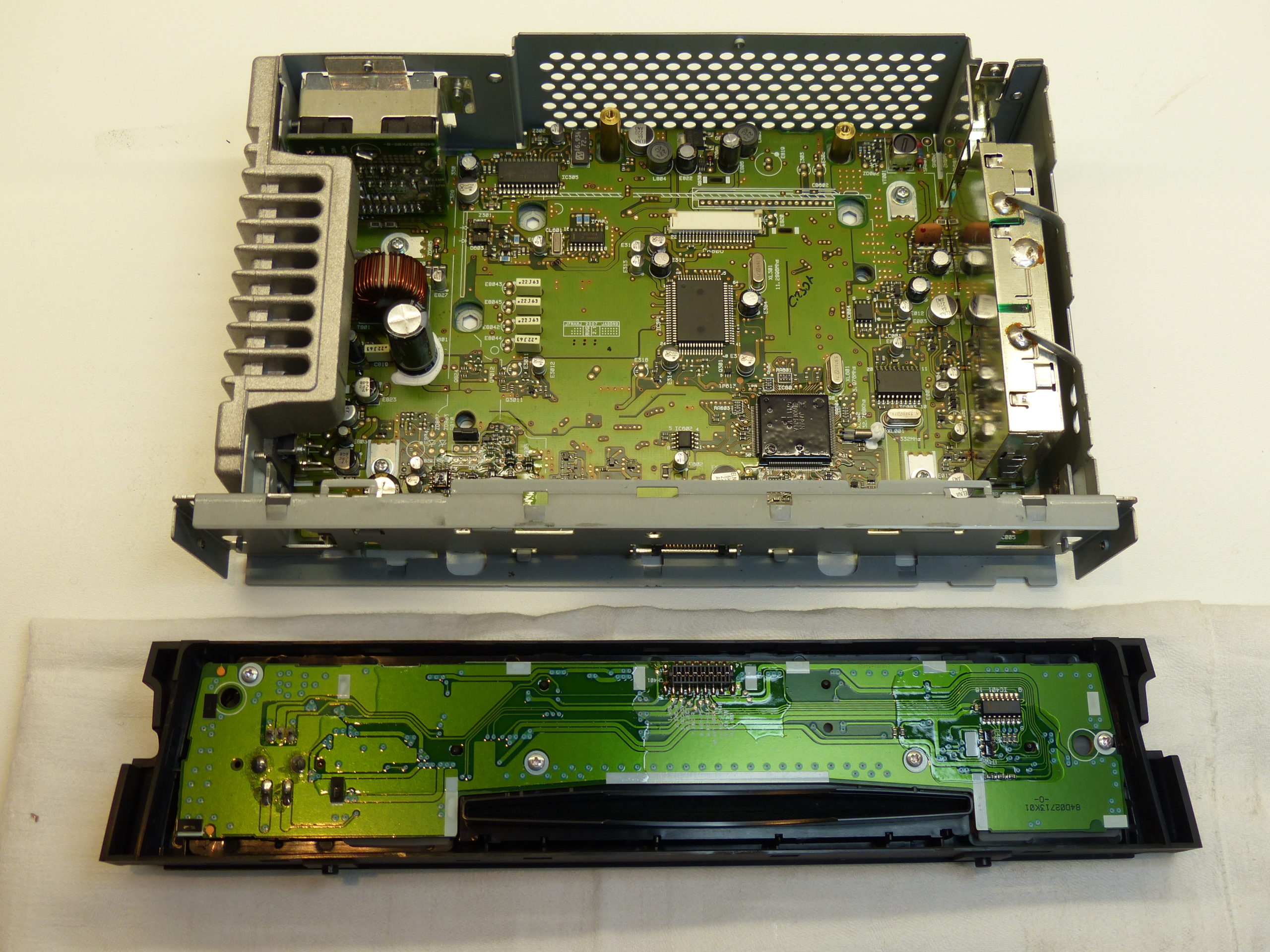
Place the bezel face down on a soft surface.

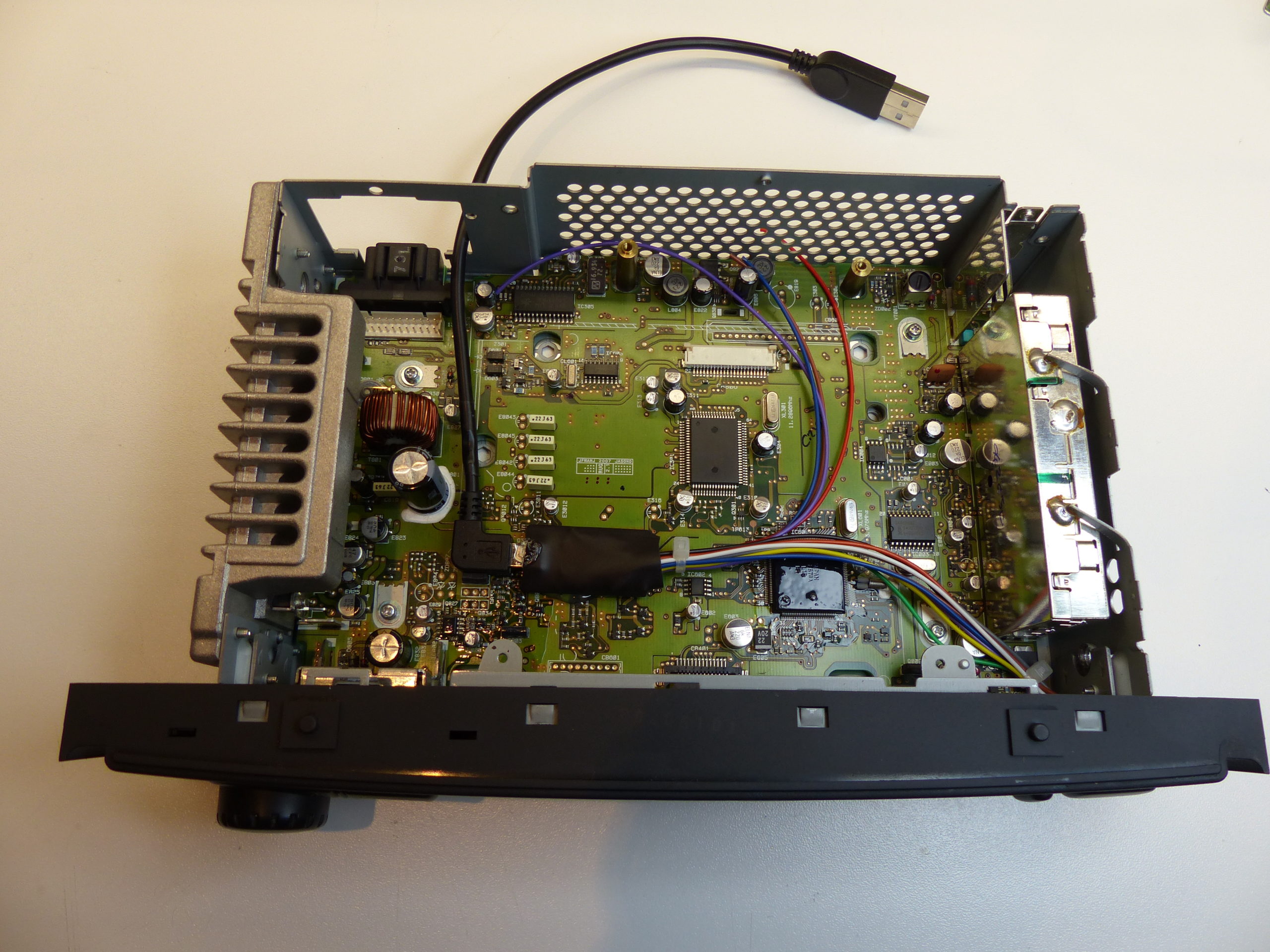
Feed the wires from the Arduino through the cutout of the front metal frame.

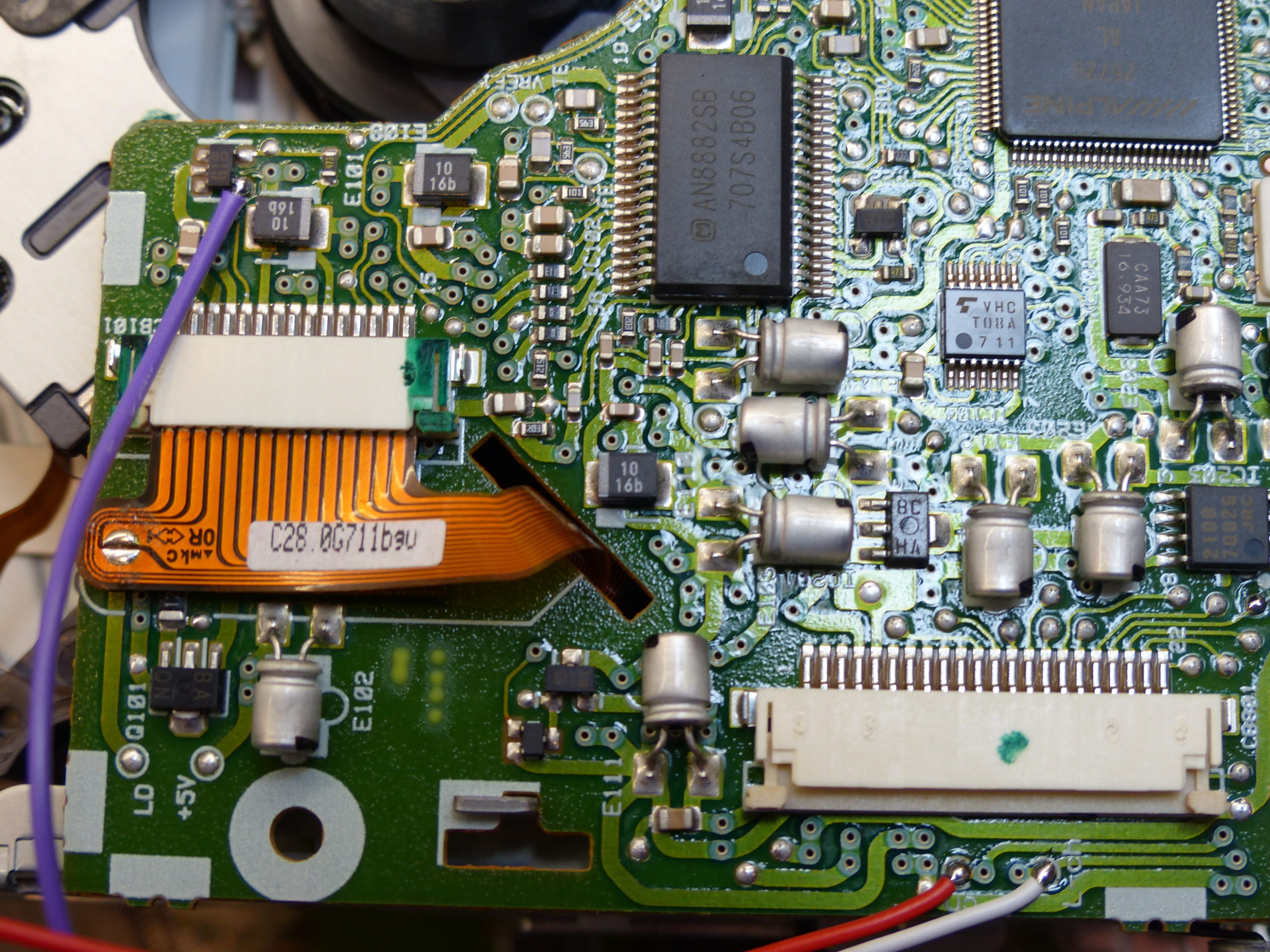
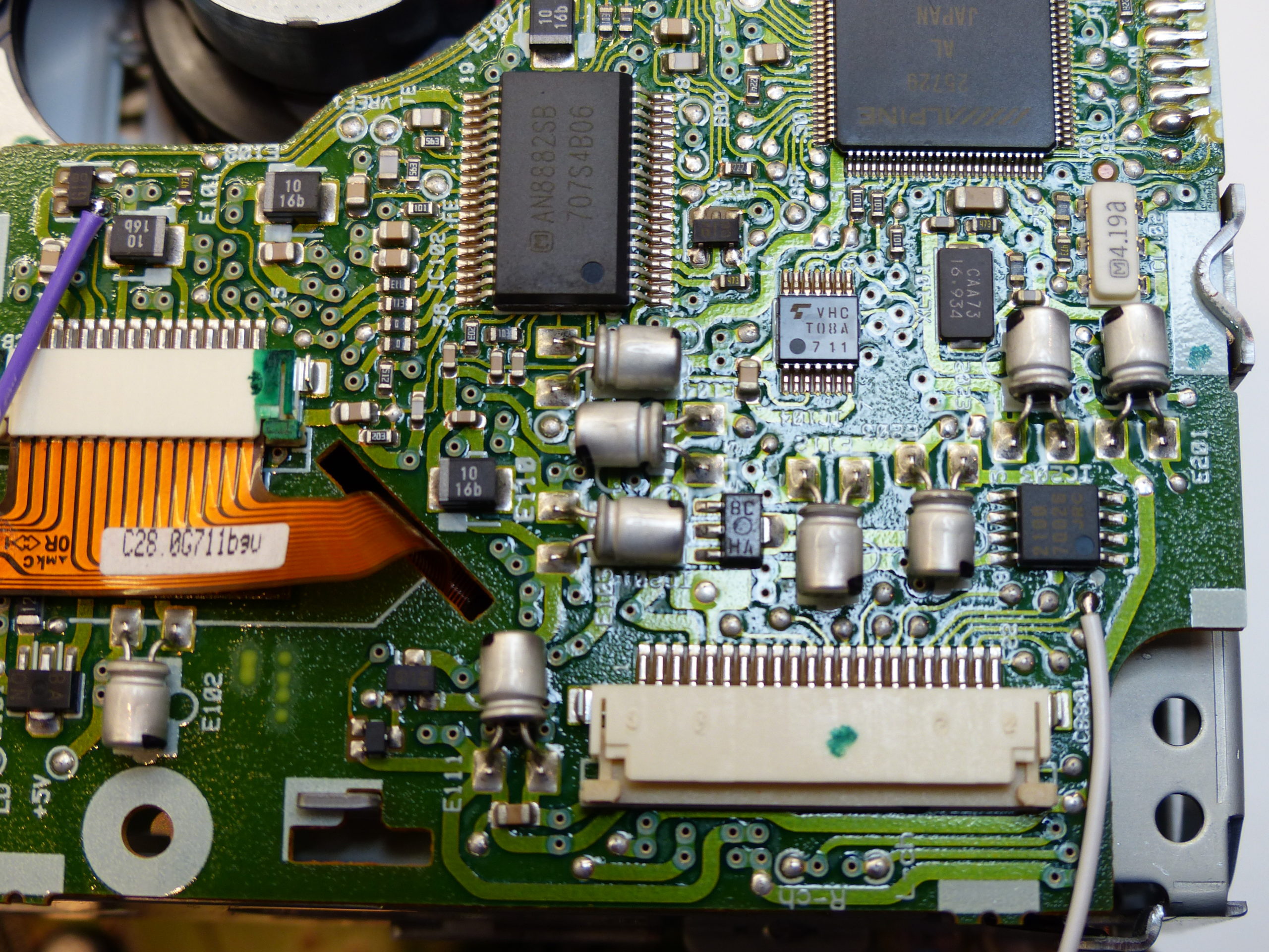
Solder the wires to the pins on the board as shown.

Take the 200mm right-angle micro-USB cable and cut the +5v (red) wire. Add a small piece of PVC tape to prevent any accidental shorts to the bare ends. This prevents the Arduino being back-fed power from the Odroid via USB, as it should only be powered from the internal supply of the CD player.

Remove the daughter-board that holds the main multi-pin connector by removing the single screw and pulling the board vertically.

Pass the USB cable through the hole and plug into the Arduino. Secure the Arduino to the main board as shown with a blob of hot-melt glue.

On the daughter-board there is a pin marked REMOCON which is the steering wheel resistor ladder input. Solder the blue wire from the Arduino to this pin.

Now plug the daughter-board back into the main board, leaving the USB cable to exit through the small gap at the side.
Push the USB cable slightly back into the case to relieve the strain on the connector, and fasten a cable-tie to act as a strain-relief.

Solder the red wire from the Arduino to the end pad of the surface mount resistor shown.
You’re probably about half-way there now, so have a cup of tea and admire your handiwork so far.
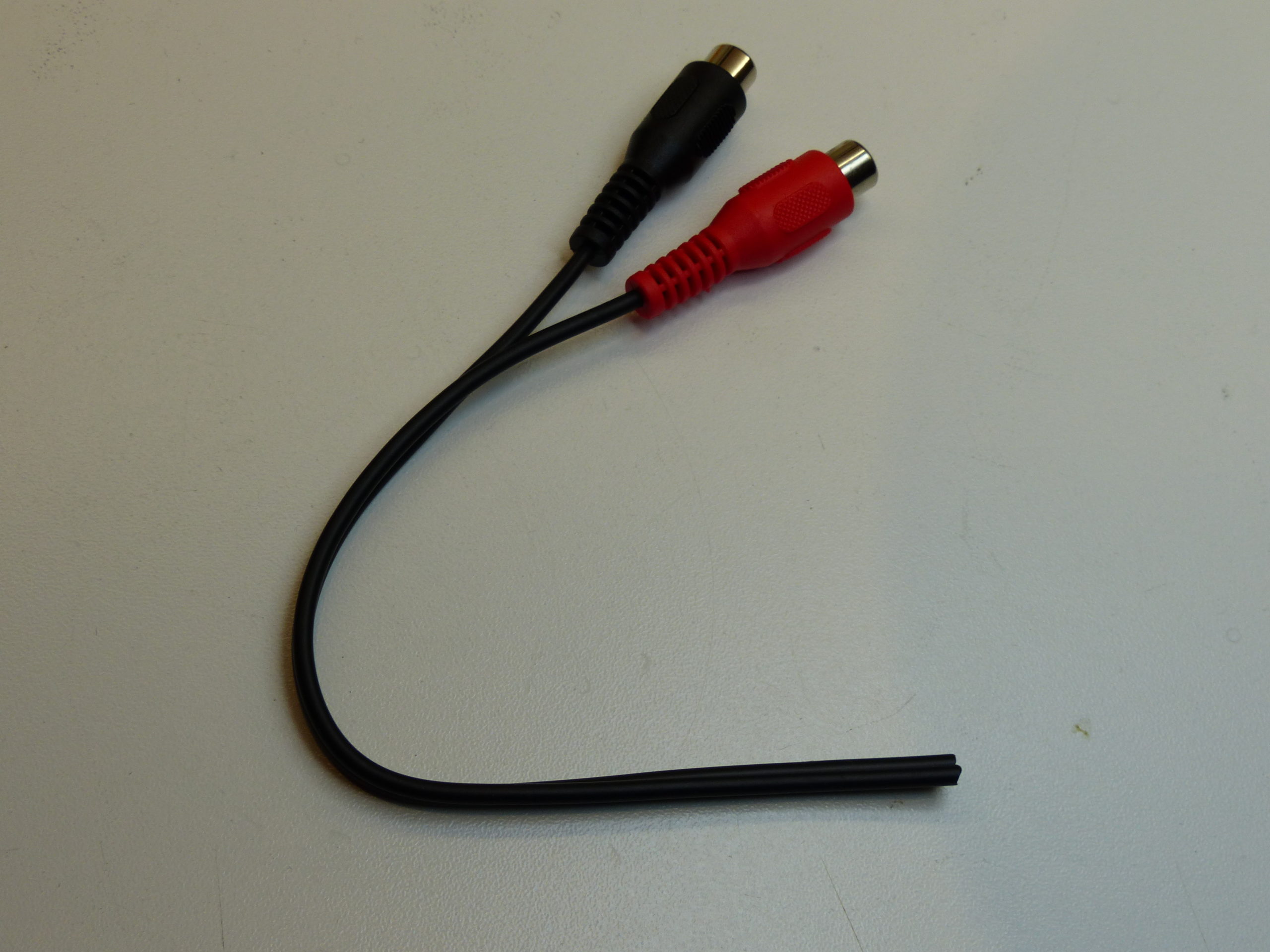
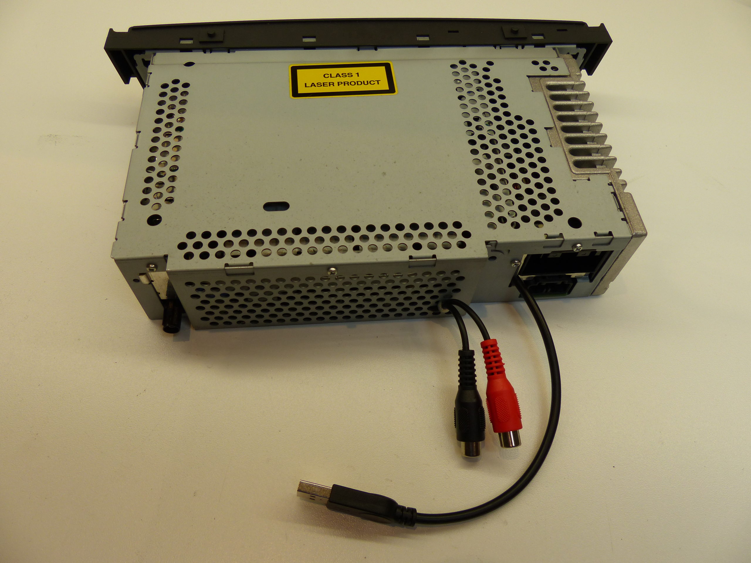
Cut off the 2 phono sockets from your phono cable.
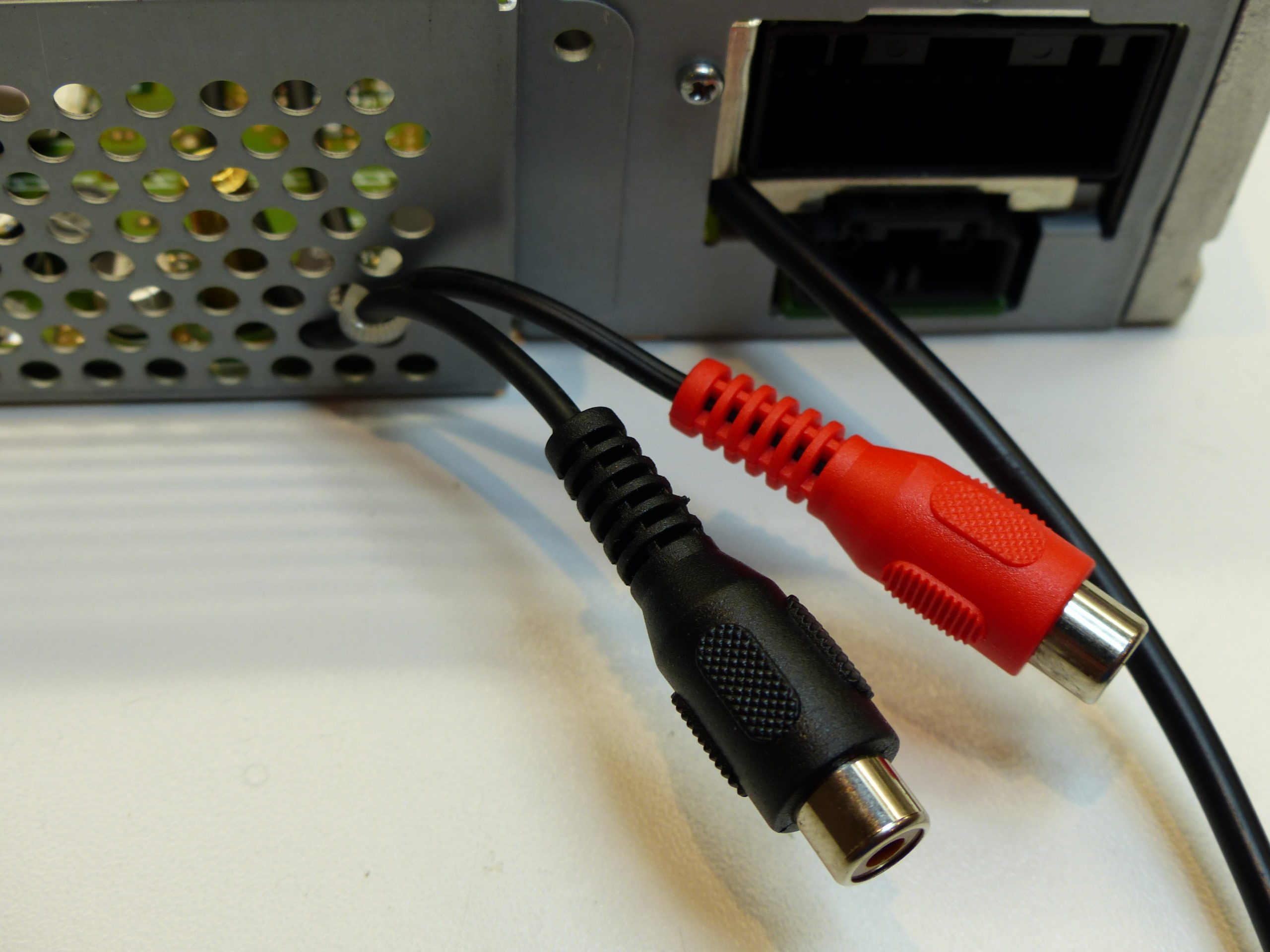
Feed them through 2 of the vent holes in the rear of the case and secure with a cable-tie. For STANDARD AUDIO equipped cars you only need one phono cable, as it will be using an SPDIF digital signal that encodes both stereo channels into a single digital stream.

Trim the insulation from the wires, join both screens and solder a length of black wire to the combined screen.
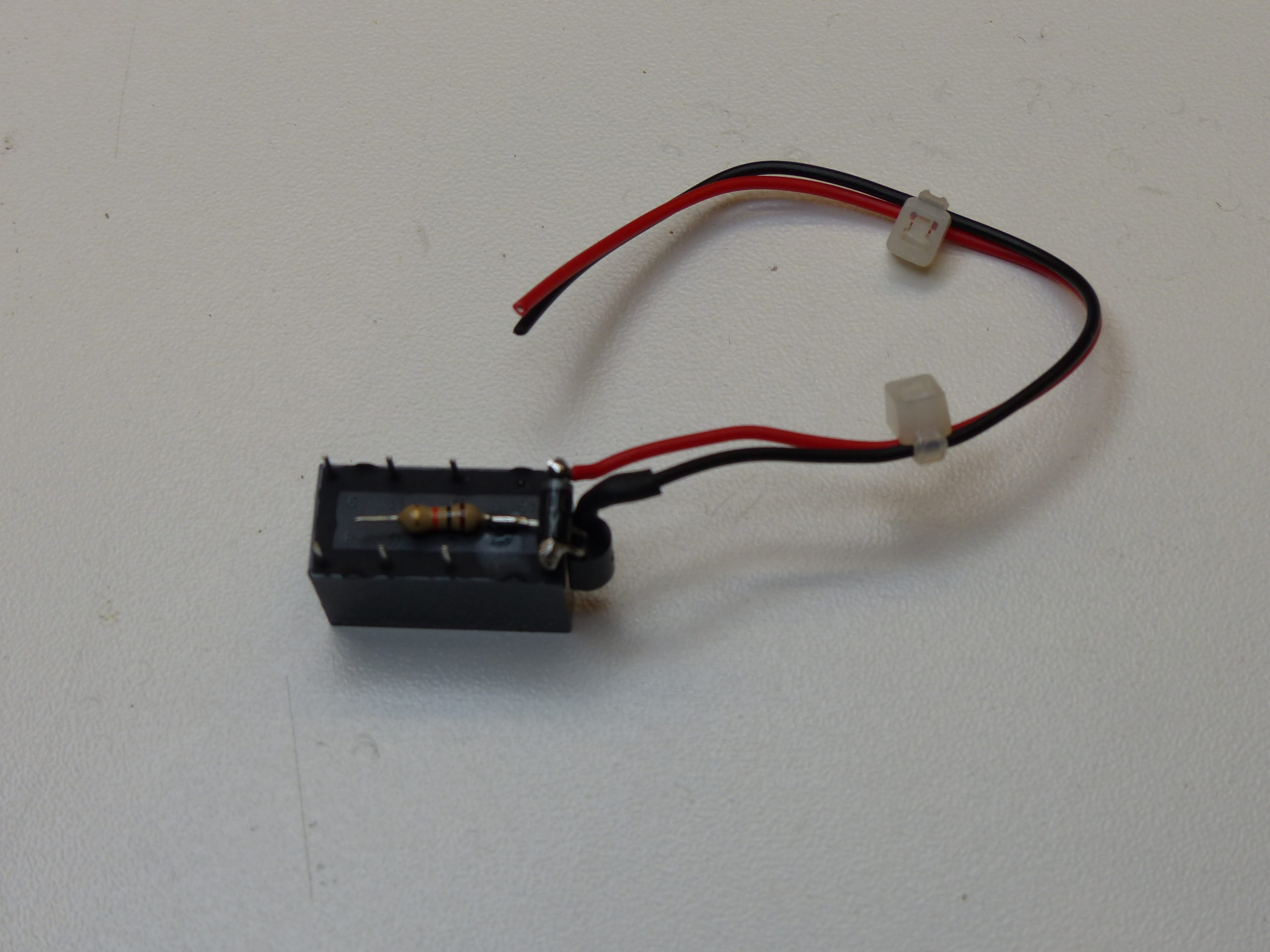
Take the relay and solder the 1N4001 diode across the coil terminals (the two slightly spaced out from the other 6), taking great care to ensure the white stripe (cathode) connection is on the left side as shown.
Then bend the legs of the BG337 transistor and solder the Collector pin to the Anode side of the diode. The Base connection should be bent down under the diode.
Solder the 10k resistor to the Base lead of the transistor.
Solder 100mm lengths of black and red wire – red to the cathode side of the diode, the black wire to the Emitter of the diode.
If you don’t know or care about the technical designations of each pin, as long as you have the flat side of the transistor case flat against the relay and everything soldered as shown, then it will be correct.

Solder the red and black wires from the relay to the ACC and GND connections on the daughter-board respectively, as well as the black screen wire from the phono cables to GND.
Solder the brown wire from the Arduino to the end of the 10k resistor and insulate with heatshrink.

PREMIUM AUDIO EQUIPPED CARS – isolate the two pins on the ribbon cable shown (pin 22 and 20) by applying a thin strip of PVC tape over the conductive pads then inserting the ribbon cable into the connector. These are the Left and Right line level signals coming from the CD transport board down to the main board.
Solder a length of white and red wire as shown, approx 80mm long.

STANDARD AUDIO EQUIPPED CARS – isolate the pin on the ribbon cable shown (pin 4) by applying a thin strip of PVC tape over the conductive pads then inserting the ribbon cable into the connector. This is the SPDIF digital signal coming from the CD transport board down to the main board.
Solder a length of white wire as shown, approx 80mm long.
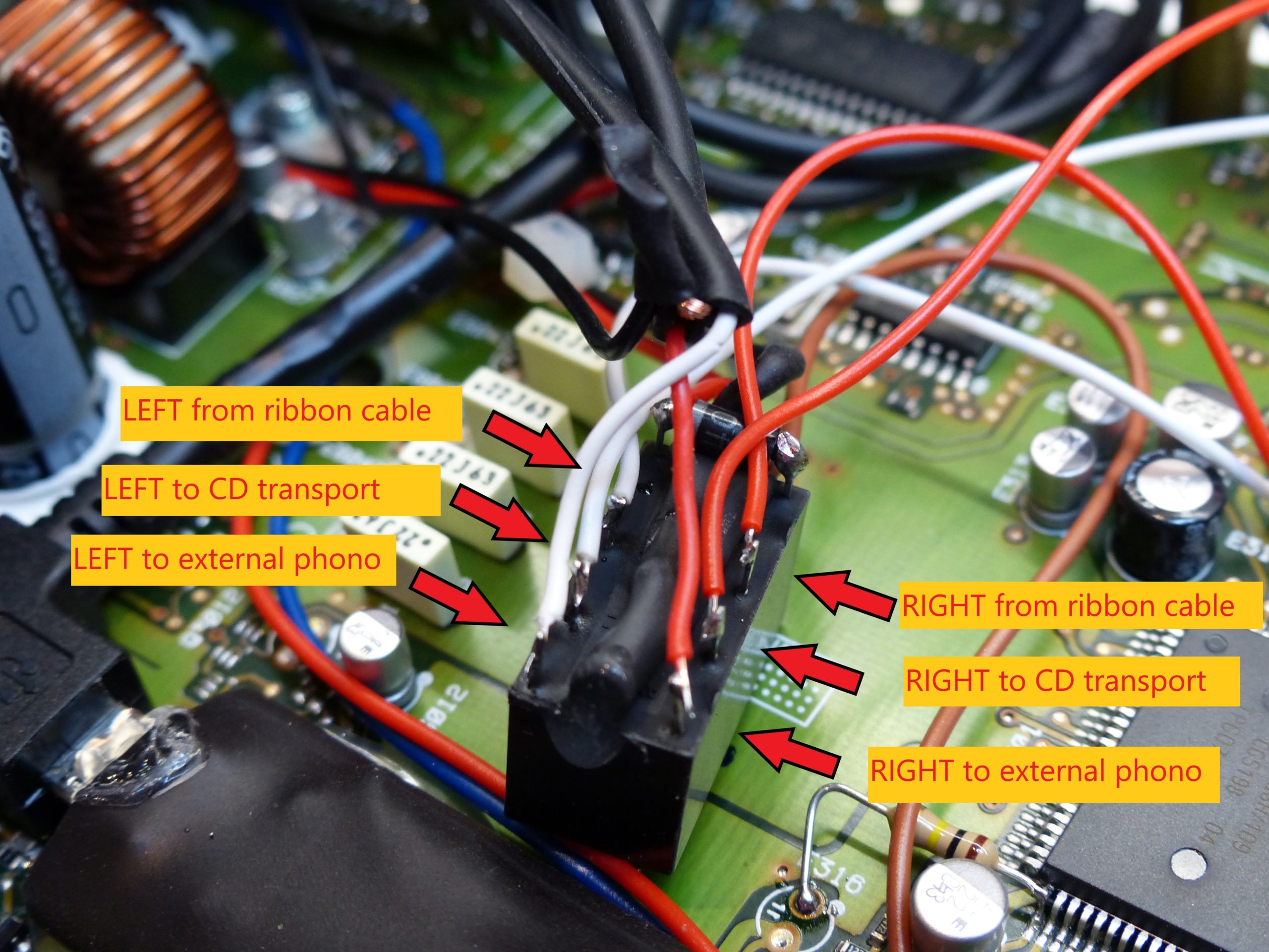
Solder the audio wires as shown. The wires ‘to CD transport’ should be approx 200mm in length.
If you have STANDARD AUDIO then you will only have the white wires, the other 3 pins will remain unconnected.
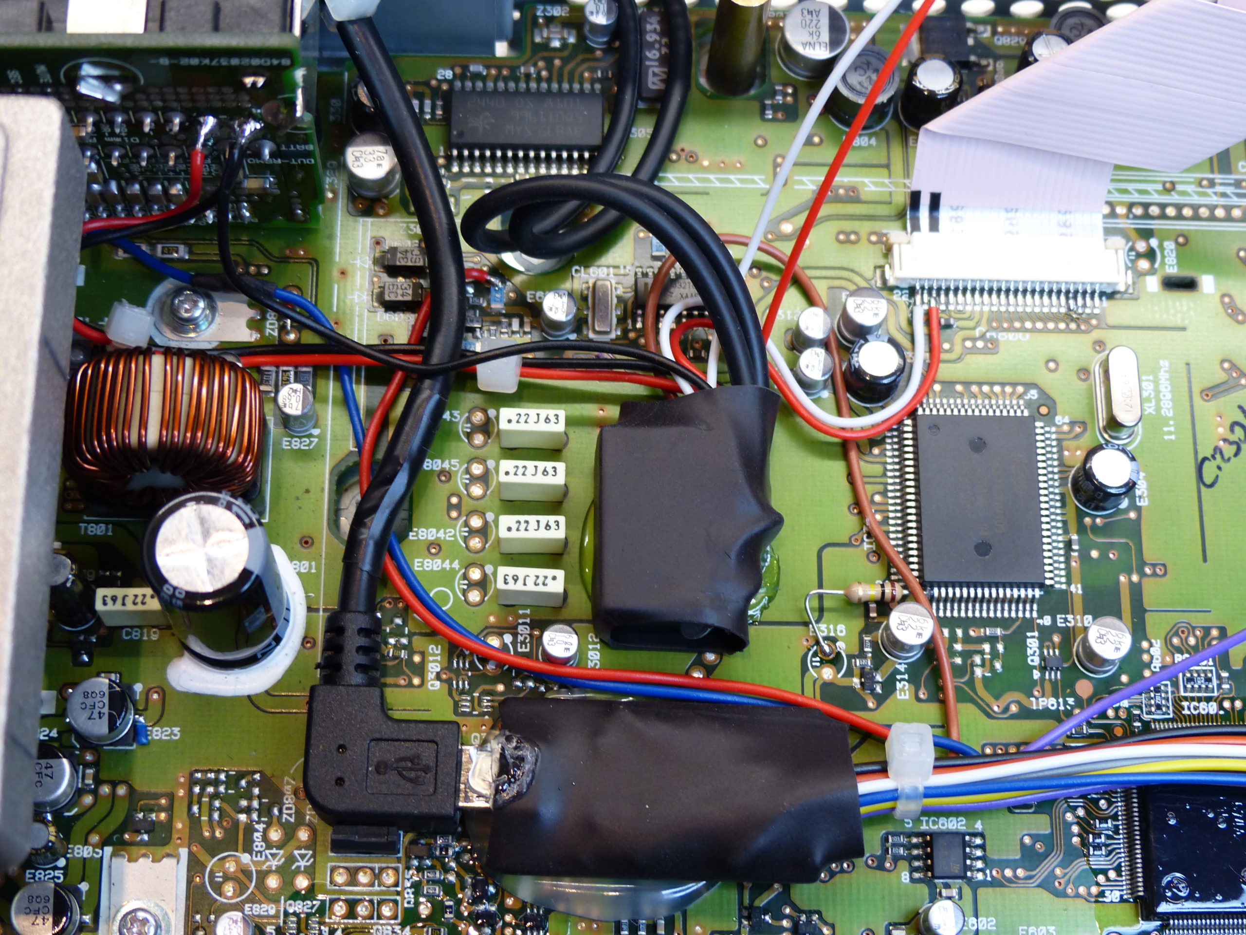
Apply some heatshrink to the relay and secure to the main board using a blob of hot-melt glue.
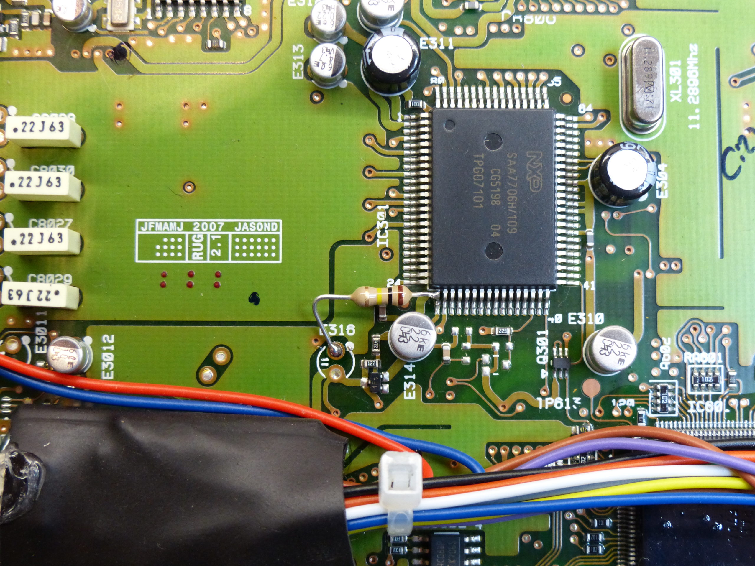
STANDARD AUDIO EQUIPPED CARS – You need to add an 100k pulldown resistor to the SPDIF line to prevent interference when switching to the aux-input. Connect the resistor as shown, between the SPDIF pin on the SAA chip and the Ground pad.
PREMIUM AUDIO EQUIPPED CARS – Solder the red and white wires from the relay to the pins shown on the CD transport board. This carries the Left & Right signal from the CD player which is used when switched to CD mode.
Solder the Purple wire from the Arduino as shown.
STANDARD AUDIO EQUIPPED CARS – Solder the single white wire from the relay to the pin shown on the CD transport board. This carries the SPDIF signal from the CD player which is used when switched to CD mode.
Solder the Purple wire from the Arduino as shown.
Reconnect the ribbon cable, place the CD transport back into place and screw back down. Then replace the top cover. You now have either a LEFT and RIGHT line level analogue audio input, or an SPDIF digital audio input, as well as a USB plug that will connect to your Android computer (or other car-pc) and send track skip/play/pause commands.

The final step is to test the system. With the USB from the CD player connected to your computer and the Arduino IDE running, open the Serial Console.
Press each button on the CD player in turn and you should see the debug information in the Serial Console indicating the keypresses.
With a CD in the drive, press CD to play the CD and you should hear the music. Press A.MEM to change to the aux-in.
If all is well, then re-comment the #debug line in the sketch by adding the // characters in front.
Due to the hardware watchdog being active which interferes with the Arduino bootloader, before you can upload the sketch again you need to reset the Arduino at the correct time. Hold MODE for around 5 seconds until you hear the relay click several times. Upload the sketch to the Arduino and as soon as the IDE indicates ‘Uploading sketch’ press CD on the player. This will trigger a reset of the Arduino which will allow the upload to take place.
It now just remains to get good quality audio out of the Odroid, and into your new Aux-input on the CD player. There is no analogue audio output on the Odroid C2 but there is an SPDIF digital output/
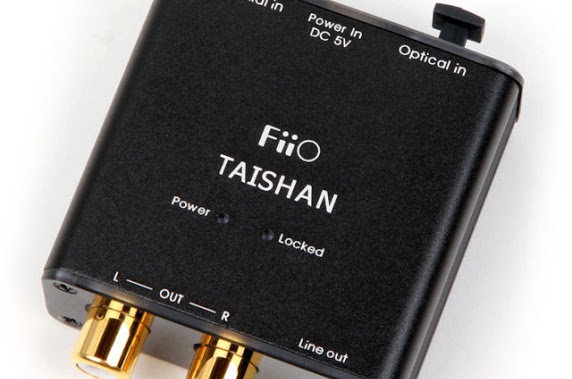
I use a Taishan Fiio D03K SPDIF Digital-To-Analogue Converter (DAC) to convert this to L/R line level audio, which is necessary for Premium Audio equipped cars.
If you just have standard audio on your Jaguar you don’t need the DAC as you can feed in the SPDIF directly.
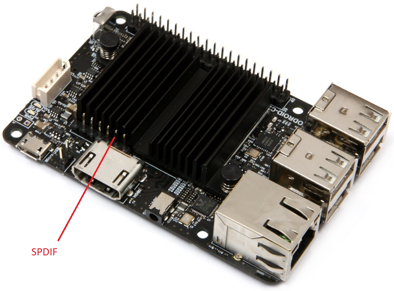
The Odroid C2 SPDIF output is shown here (second pin from the right, behind the HDMI connector). Connect this pin to the centre pin of the Co-axial phono connector SPDIF input of the DAC, or directly to the SPDIF aux-input of the CD player if you’ve done the digital mod, and the pin to the right (centre of the HDMI socket) is Ground.
Then enjoy your music 🙂