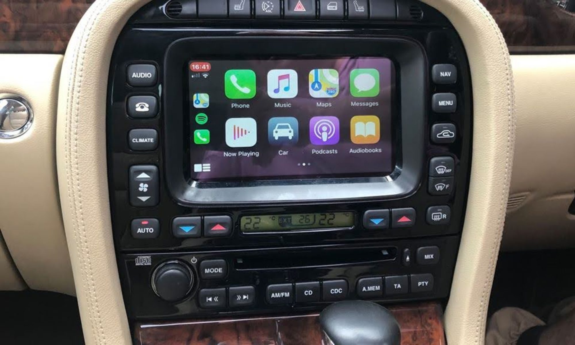
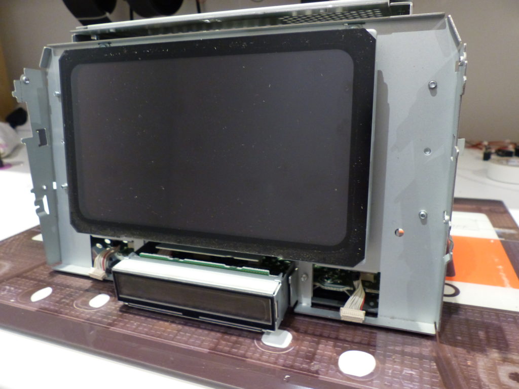
There several variants of touchscreen head unit dependent on features and car model, however the main physical differences that affect the conversions are between the TV equipped units, and the non-TV units.
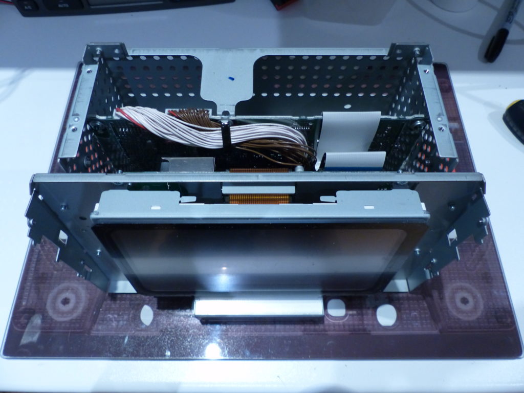
On a TV unit the television board underneath the metal back panel can be completely removed, leaving room for the new video driver and Arduino microcontroller board. On the non-TV units the metal back panel isn’t removable but there is room on the inside of the case to mount the necessary new boards.
You will need several components, which are detailed below, including a 7″ capacitive touch overlay such as this one: https://www.ebay.co.uk/itm/292601144432
The steps below show the modification to a non-TV unit:
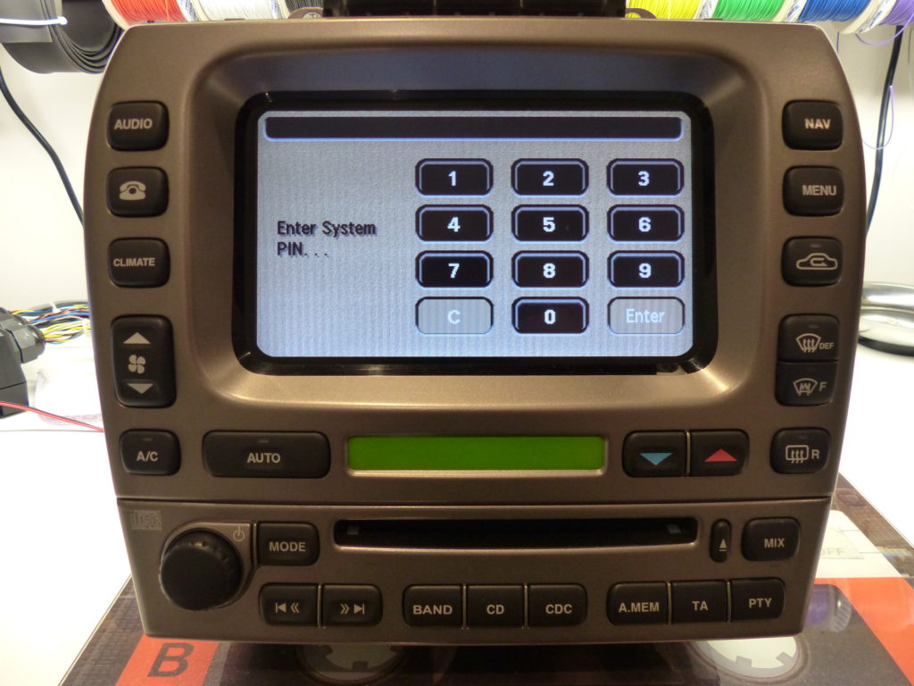
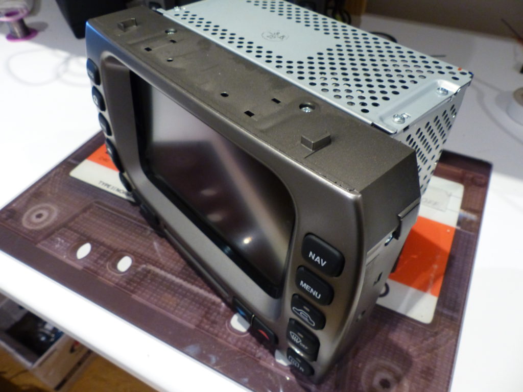
Here is a touchscreen and CD player from an X-Type. When powered up you may be prompted to enter the system PIN (not in all country variants). This is the 4 digit radio code that is normally printed on a card with the user guide.
If the PIN is not available, on some early models you can bypass the code by pressing >>, A.MEM and PTY at the same time.
If this does not work then there are services available on eBay to provide the PIN if you supply the serial number engraved on the bottom of the CD player
The front plastic bezel is secured by 6 screws. Remove the screws then prise the left and right sides away towards the front of the unit. There are two multiway connectors attaching the board inside the bezel, carefully unplug these.
The top metal cover is attached by 4 screws. Remove the panel, and unplug the copper colour ribbon cable going from the LCD panel to the video board. On the left side are two connectors with pink/white wires for the LCD backlight – unplug these.
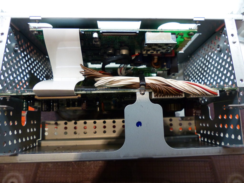
Disconnect the white ribbon cable from the middle board, and also disconnect the 2 connectors with brown and white wires.
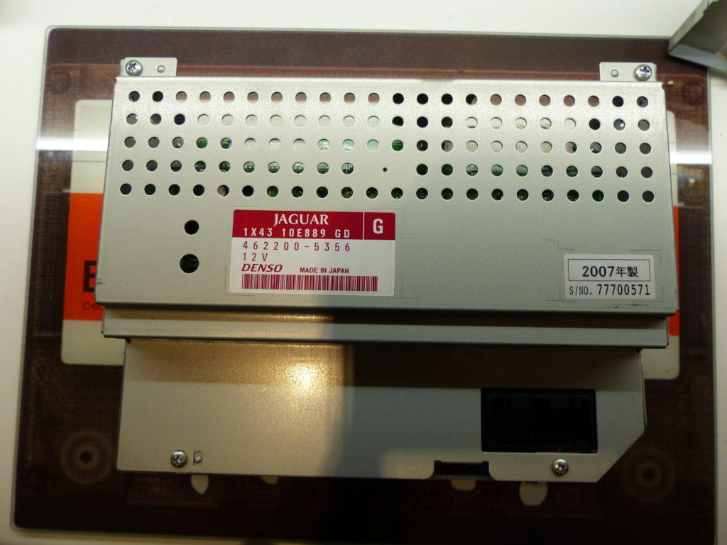
Remove the 4 screws from the rear of the unit and separate the two halves.

Cut off one of the plugs from the LCD panel, and solder a 470 Ohm 1/4w resistor across the legs as shown, then insulate with a small piece of heatshrink.
Plug this into one of the backlight connectors on the video board. This is a dummy load to avoid the video board detecting that the original LCD panel is no longer connected, which would otherwise trip a fault code.
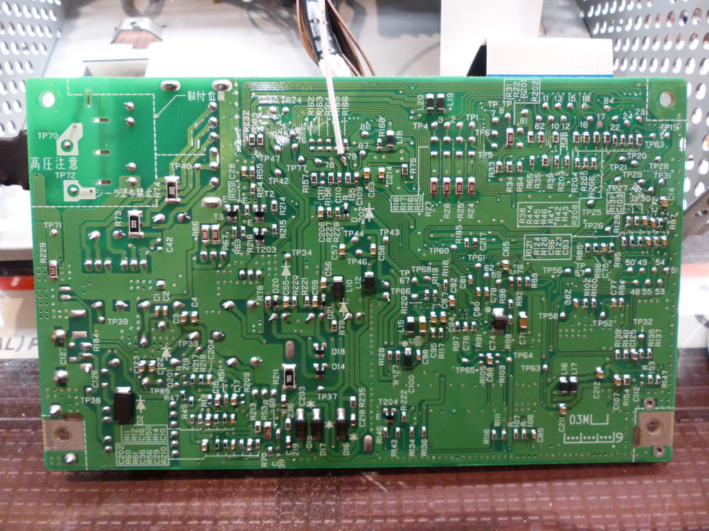
Remove the video board and turn upside down.
You will need a 10-pin molex plug assembly such as this, with 2mm pitch pins: https://www.ebay.co.uk/itm/272629433388
Remove the white cable from the connector assembly and solder the end to to TP79. This is the Sync signal that will plug into the new RTD video board later.
Now screw the board back into position.
Next we have to add a relay to the original touch matrix so that the Arduino can switch off the original touch and switch on the new capacitive overlay used by the Odroid. Remove the short multipin wiring connector from the right-side of the unit (with the screen end facing away from you).
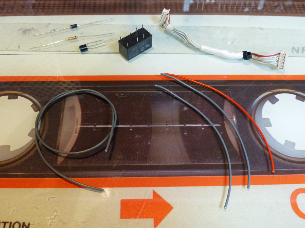
You will require the following
- 12v DPDT relay (e.g. https://www.switchelectronics.co.uk/subminiature-pcb-12v-signal-relay-dpdt )
- 1N4007 diode
- BC337 NPN transistor
- 10KOhm 1/4w resistor
- Wire
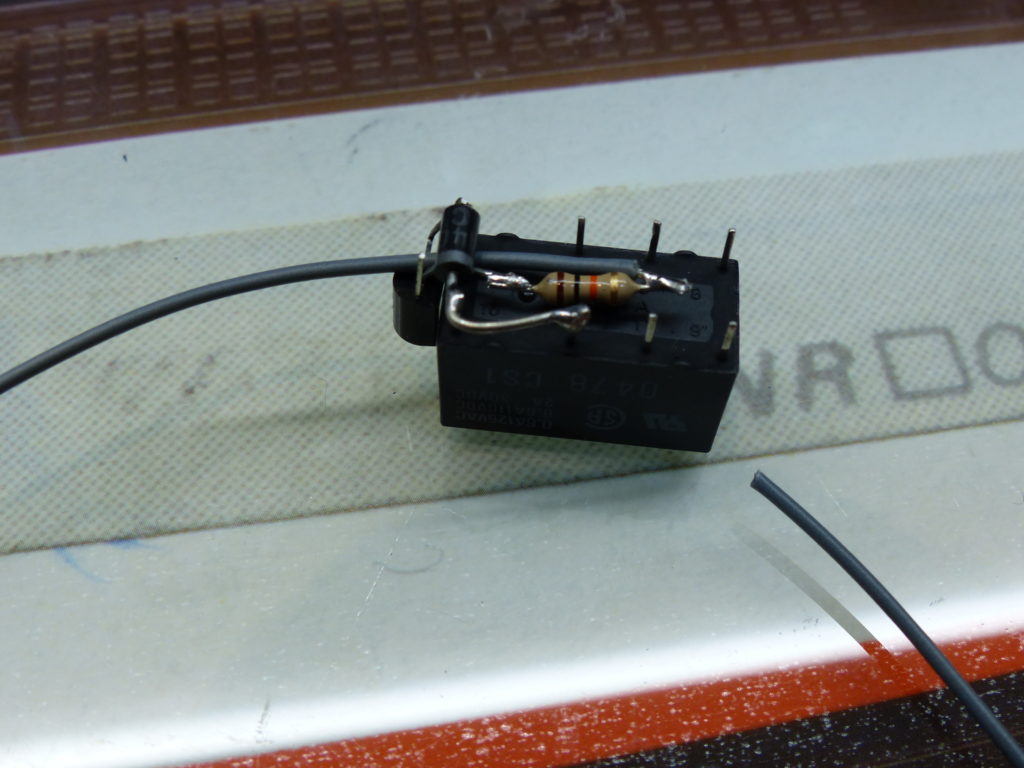
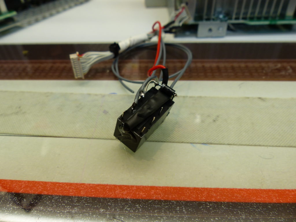
Solder the transistor, diode and resistor as shown.
The grey wire will go to one of the Arduino digital outputs to control the relay switching on and off. The set of terminals nearest to the camera will break the original touch matrix power supply when the relay is activated, and the other pole of the relay is used to switch in the power to the USB touch controller.
With some wire, extend the connections as shown.
Note that the RED wire is actually 0v, and the GREY wires are +12v.
The RED wire is spliced into to take a 0v reference to the transistor, the GREY +12v from the plug side of the cable (3rd wire in from the opposite end of the red one) goes to relay coil and COM side of the relay. The NC terminal of the relay then connects back to the other end of the cut cable to send the new switched feed to the bezel front panel.
Next get the USB cable for the capacitive touch controller, and cut into the red +5v supply. Solder these across the COM and NO terminals on the other pole of the relay.
Reinstall the multi-pin connector, securing the relay with a cable tie and routing the USB touchscreen cable so that the panel end goes through the front panel, and the USB plug is routed towards the back of the chassis.
The grey wire from the relay will connect to the Arduino in a later stage.
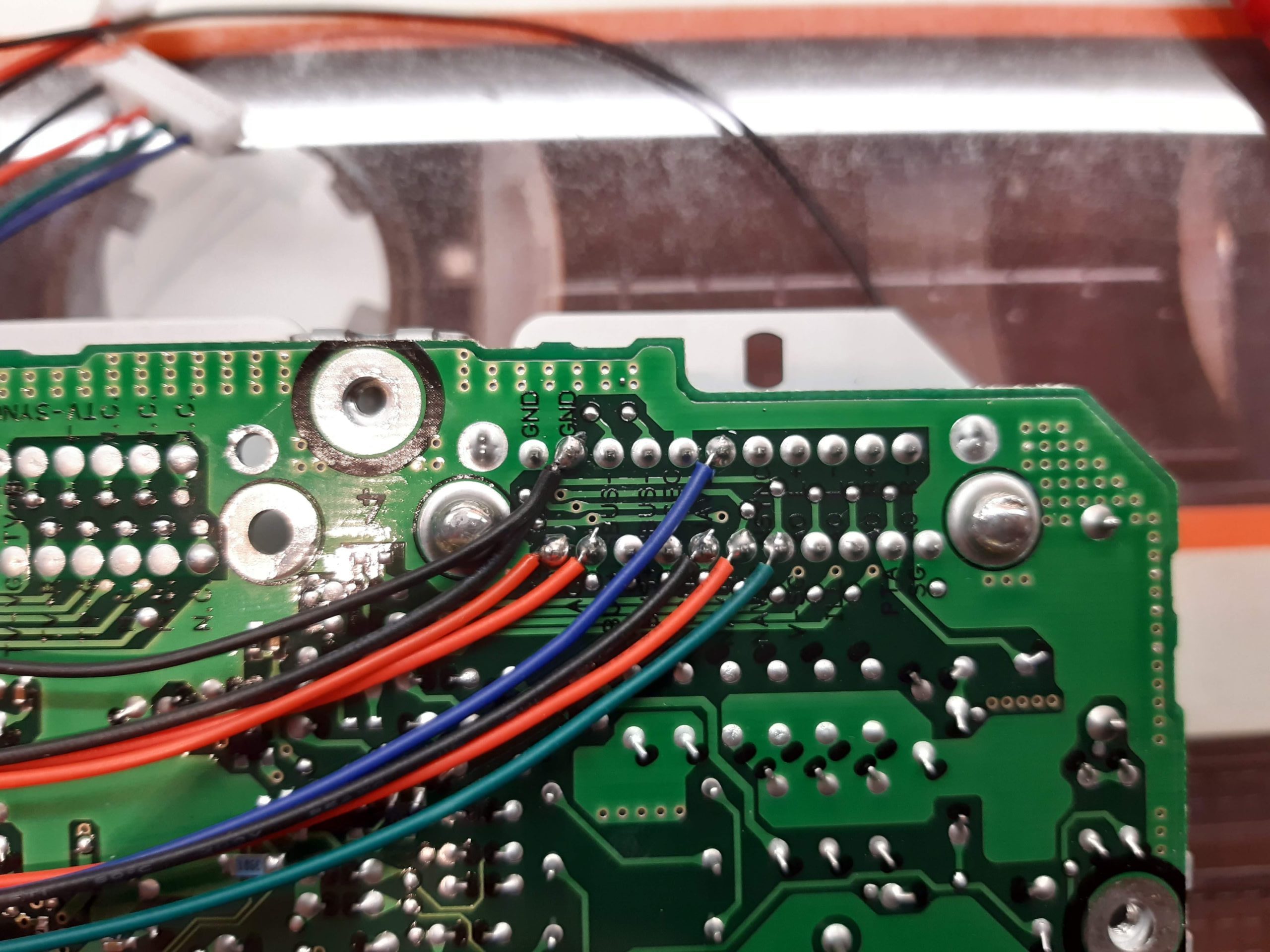
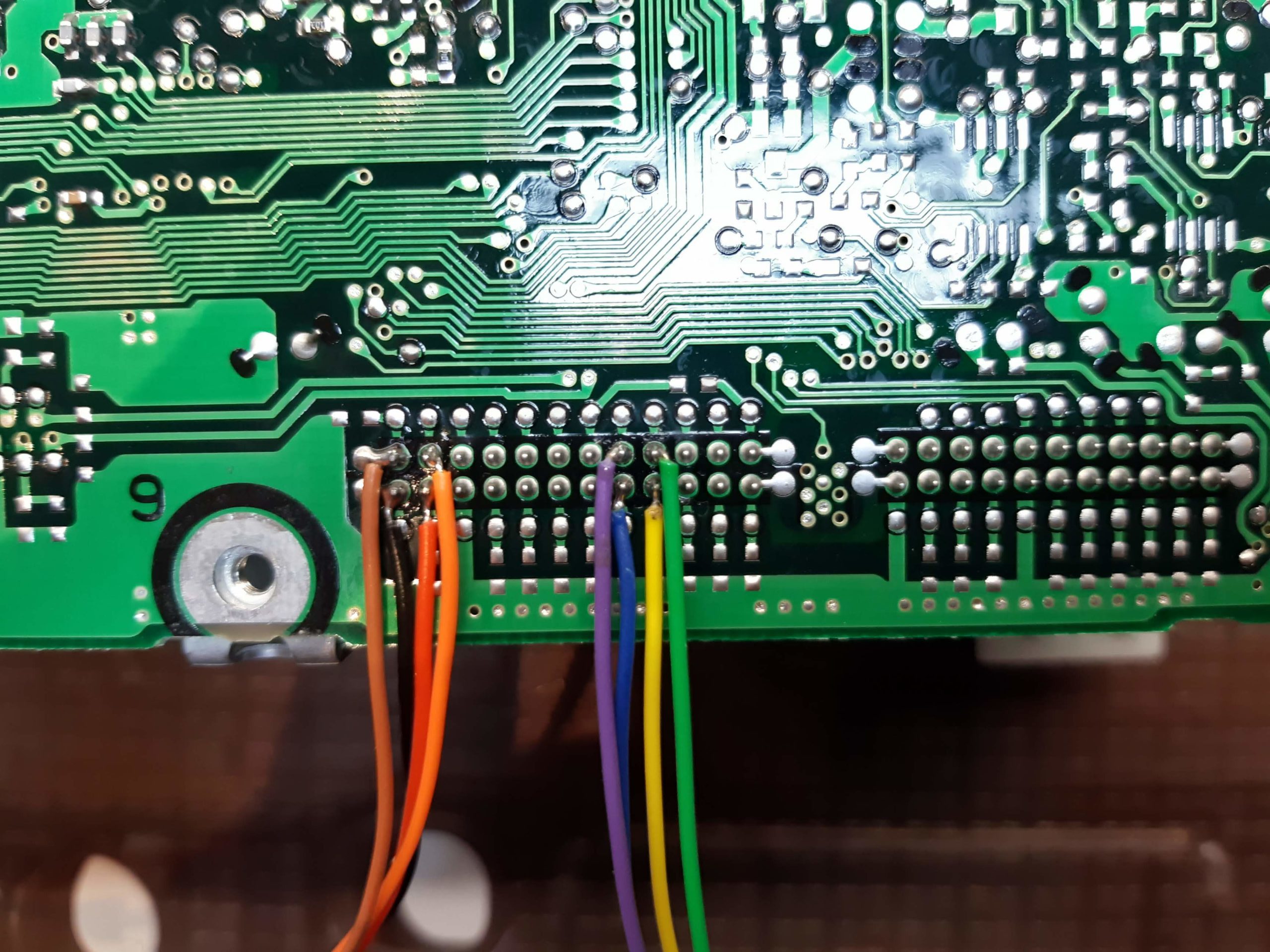
Now the connections need to be soldered to the rear of the original control board, to pick up switched accessory power, permanent 12v power, RGBS video signals and the button matrix connections.
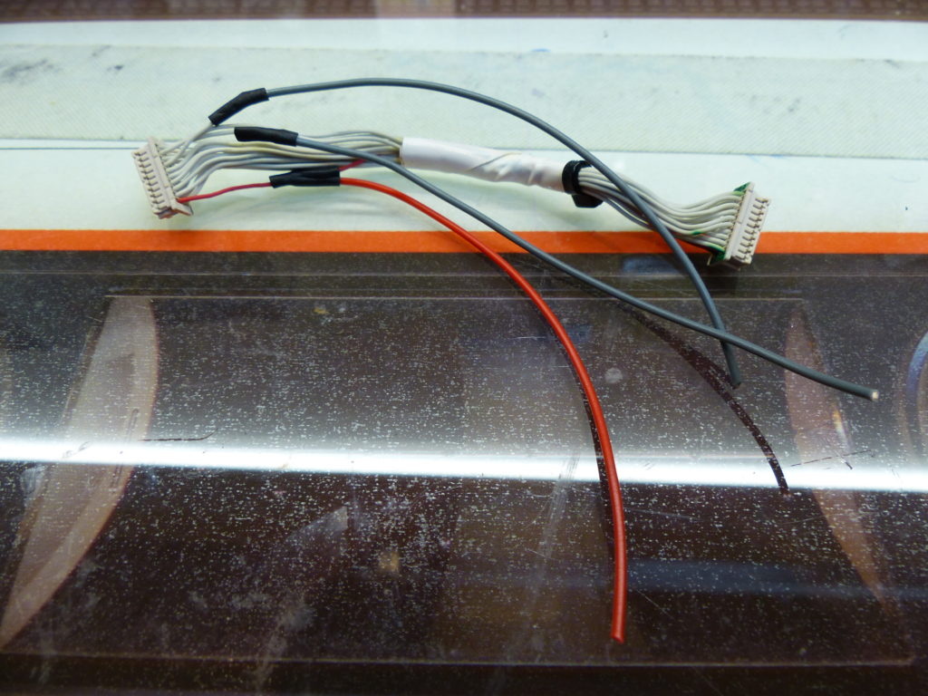
A 10-pin and 4-pin molex connector have to be soldered to the board, which will plug into the RTD video board, as well as 2 x 4 pin connections for the button matrix connectors.
Remove all existing wires from the 10-pin molex connector and re-insert as shown. These are the RGB and video Ground connections. The white Sync wire you soldered earlier will plug back in here at a later stage.
Remove all existing wires from the 4-pin molex connector and re-insert as shown. These are the +12v switched accessory power and ground that will go to the RTD video board.
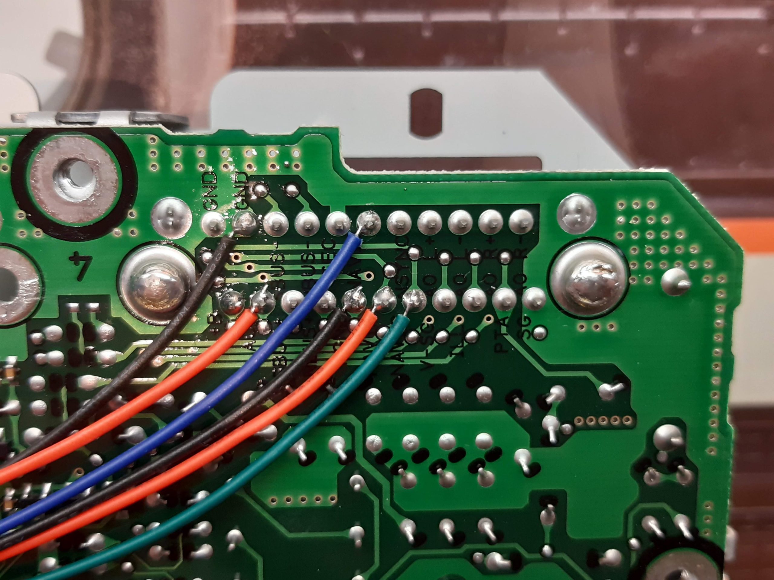
Solder the wires from the 10-pin connector as shown. These connect to the RGB and video ground pins.
Now add the red and black wires from the 4-pin connector, which are the 12v supply and ground to the RTD board.
Add an extra 200mm length of red and black wire which will be the supply to the Arduino via the voltage regulator.
Now solder the button matrix connections to the 4-pin right-angled headers you previously made, these will connect to the Arduino.
Please continue to the Video board programming and modification page
