

The new LCD panel is mounted to a 5mm thick Acrylic backplate that is laser cut. If you need a company who can supply laser cut material try https://laser.makersmarket.xyz/
Note the orientation – the single notch is on the left, the double notches on the right. The wide tabs are at the top, and the narrow tabs at the bottom.
Each of the 3mm holes should be counter-bored by approx 2mm as the screws need to be recessed.

The 7″ LCD panel and Capacitive touch panel are shown here. The Capacitive panel needs to be bonded to the face of the LCD panel.

Some touch panels come with double-sided adhesive tape already applied. If not, apply 2mm width double-sided self-adhesive tape to the perimiter of the LCD panel.
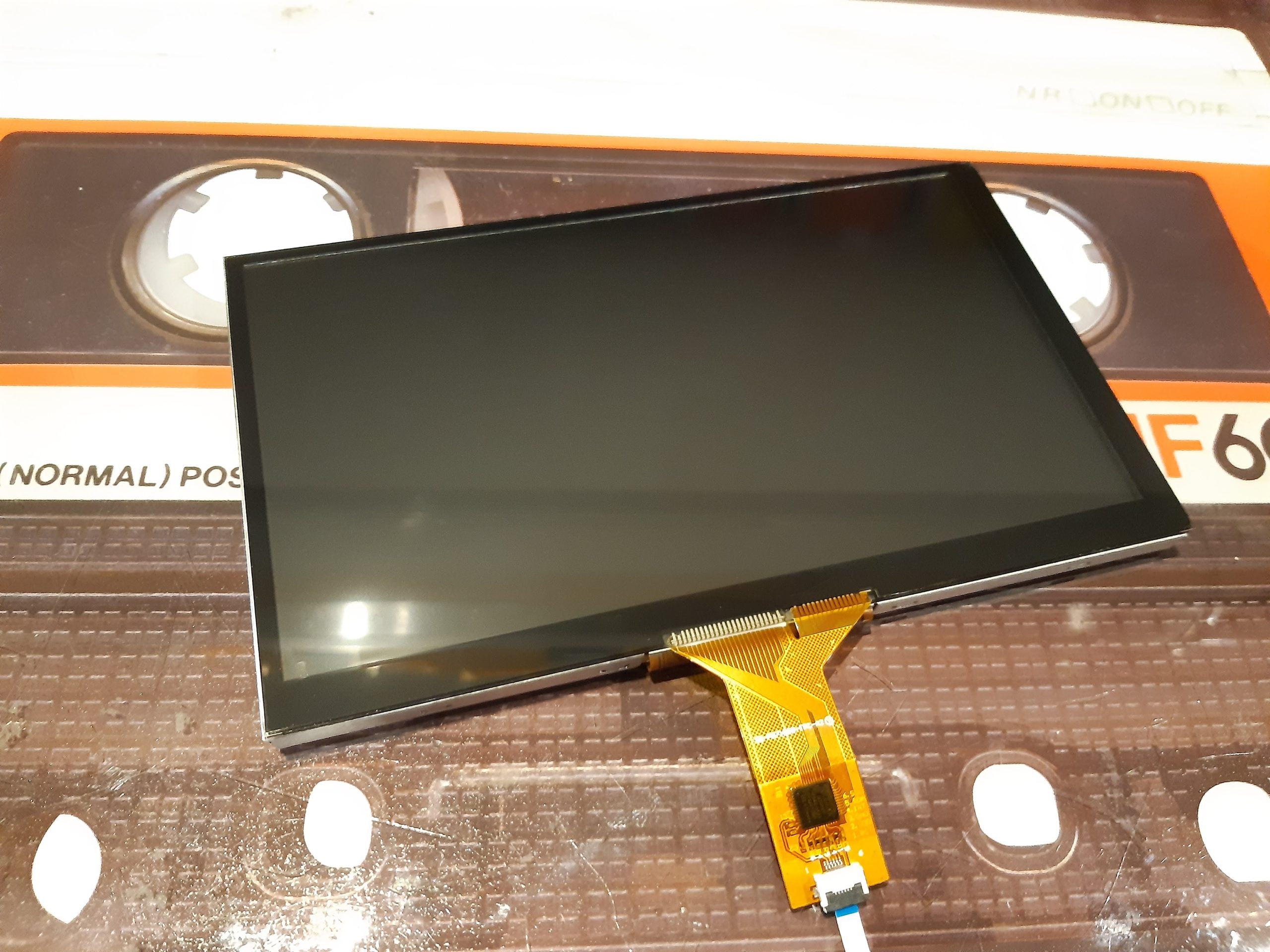
Remove the outer protective film from the touch panel (a secondary protective layer usually is present which can be removed later), and the protective film from the LCD screen.
Bond both parts together ensuring the surfaces are dust-free. This must be done carefully to ensure correct alignment. The black surround of the touch panel should cover the metal surround of the LCD panel.
The new screen assembly must now be bonded to the acrylic backplate. Apply some strips of wider self-adhesive double-sided tape to the backplate.

Bond the assembly to the backplate, taking great care to align the LCD panel edges to the guide edges of the backplate. This process is critical, and the alignment has to be accurate to ensure correct positioning within the screen bezel. I recommend not applying final pressure until the assembly is in place and the bezel test fitted to ensure correct alignment.
NOTE: Remember to release the ribbon cable from the back of the LCD panel before bonding to the backplate, to ensure it is not trapped in-between!
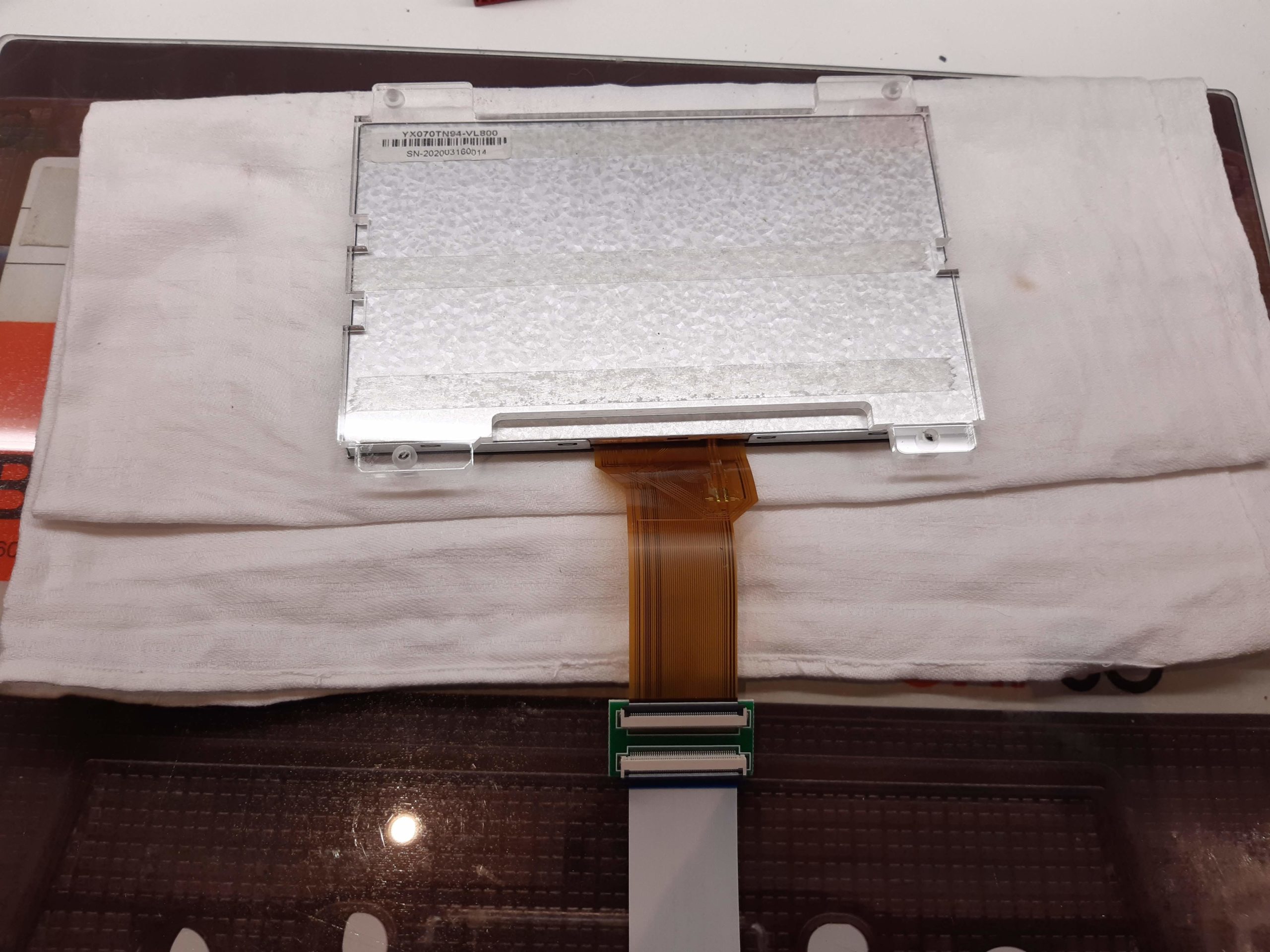
Turn the new assembly over and protect from scratches on a soft surface. Attach the 50-pin FPC coupler and a 200mm ribbon extension to the LCD FPC.
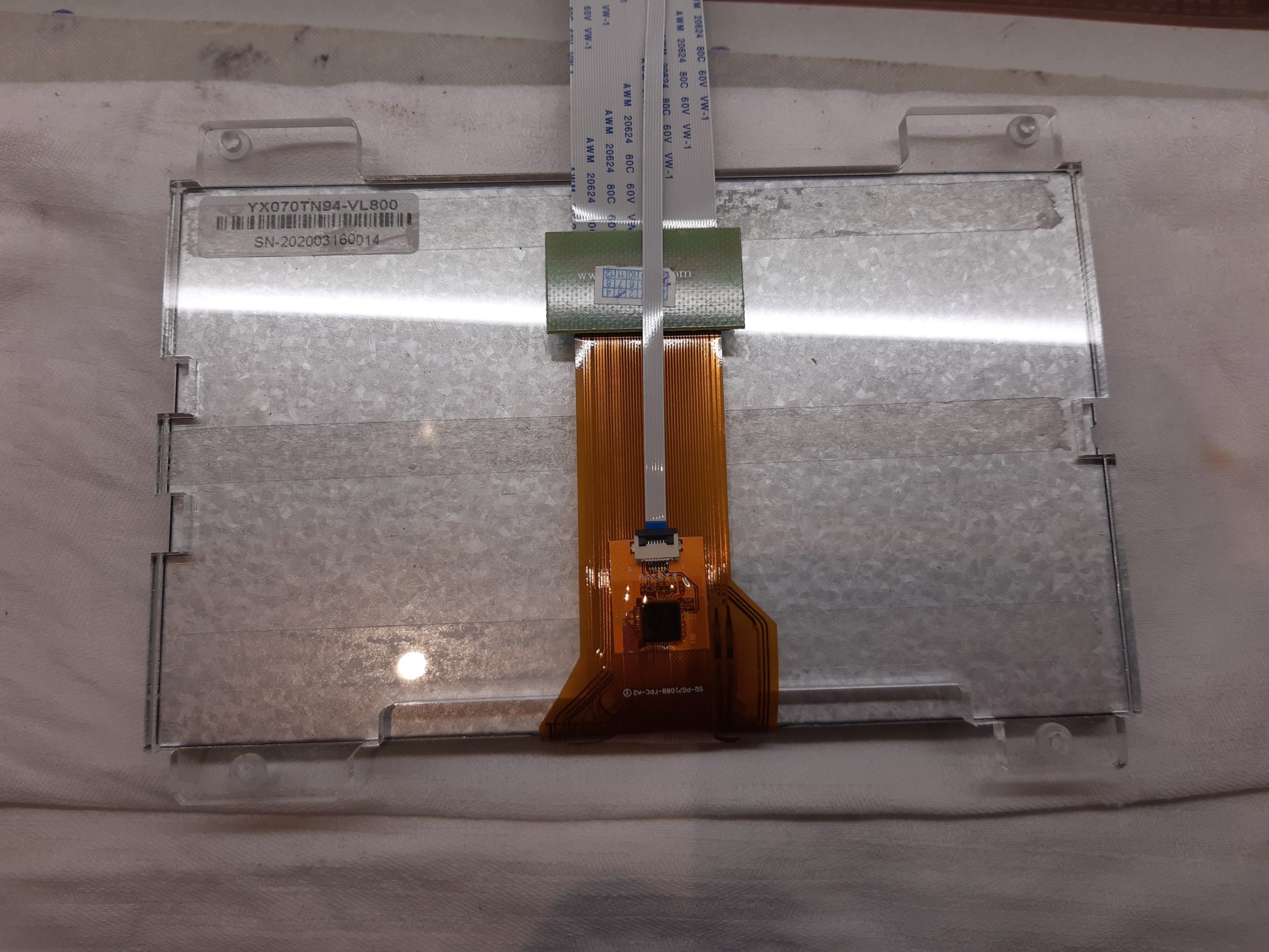
Secure the 50-pin extension to the backplate using a double-sided foam pad, and secure the capacitive touch ribbon to the LCD ribbon using the integral adhesive pad.

Attach the capacitive touch controller to the touch panel FPC cable, and secure to the backplate with a double-sided self-adhesive foam pad.

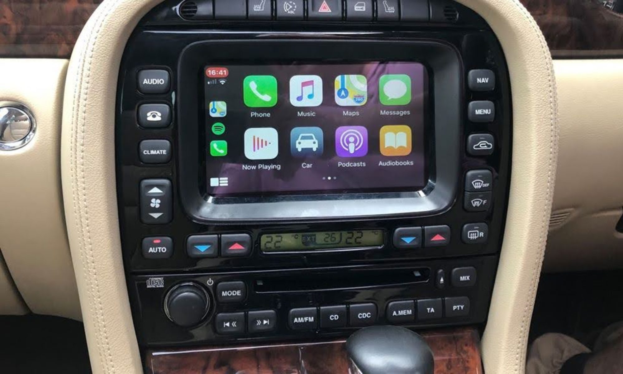
The new screen assembly will attach to the original mounting holes on the front panel of the unit.
You will need 4 x 10mm nylon spacers with 6mm M3 thread, and 4 x M3 nylon washers, to take the total height up to 11mm.

Attach the washers and spacers to the 4 x LCD mounting holes.
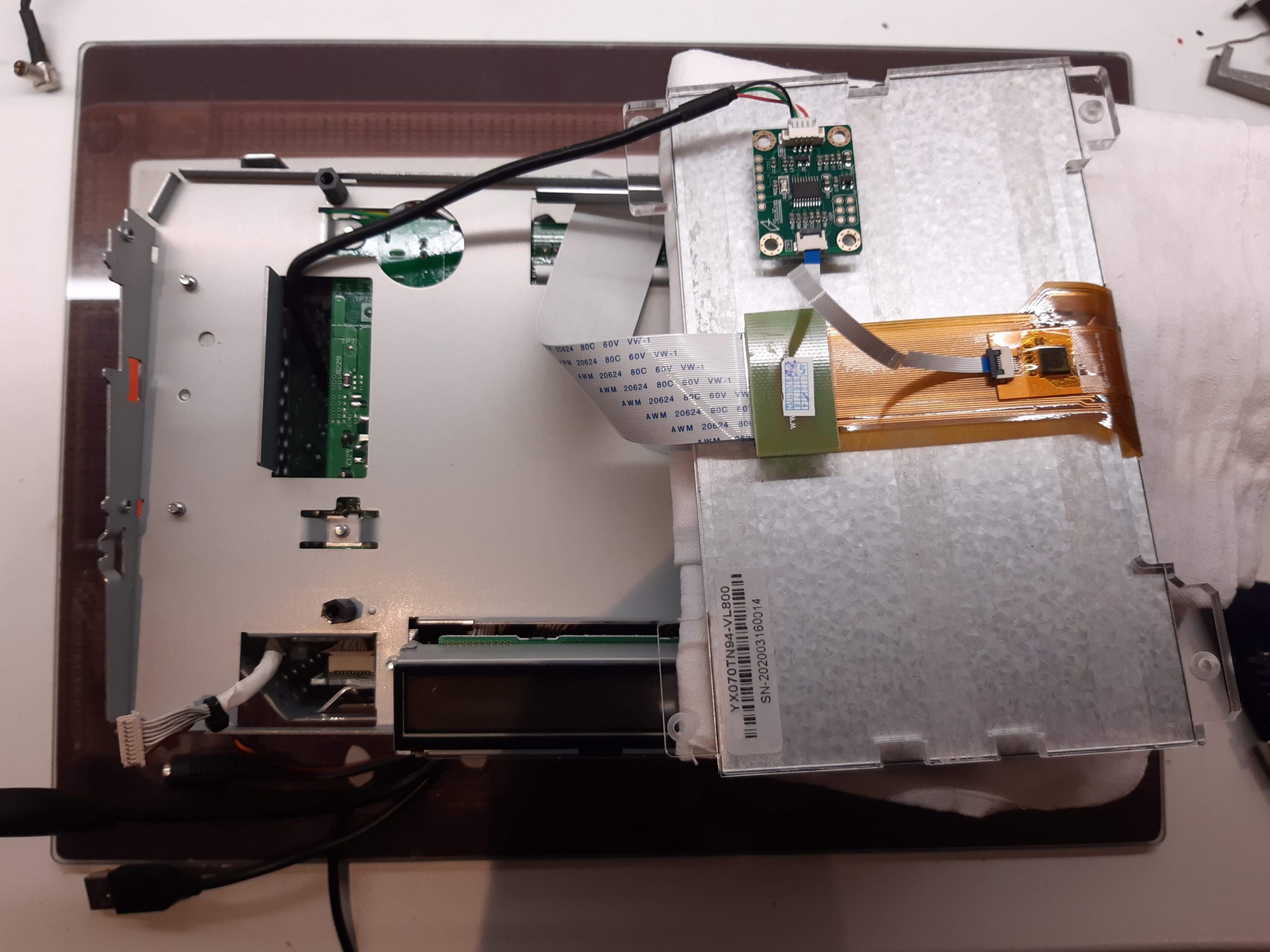
Support the LCD panel assembly on a soft surface, and feed the ribbon cable through the original cutout in the front panel. Plug the touchscreen connection into the capacitive touch controller.

Fasten the backplate in place with 4 x 8mm M3 nylon screws.
Re-fit the bezel and assess the alignment of the LCD/touch panel within the screen opening. If satisfied, apply moderate even pressure to the face of the touchscreen to ensure a secure bond with the adhesive. Don’t forget to remove the secondary protective film before final assembly.

Attach the LCD FPC connector to the RTD board and push the excess into the chassis.