

The Arduino microcontroller is a core part of the modification and takes care of the following:
- Scanning all the hard buttons around the touchscreen for key presses
- Controls the input on the video controller board via i2c
- Monitors the ignition and interior light state to control the power to the Odroid computer
- Interfaces with the original touchscreen brightness control to control the backlight level of the new LCD panel
The connections to the ignition power state (Accessory power, or ACC) and the interior light are made via an opto-isolator to protect the input of the Arduino and convert the levels from 12v power to the 5v digital input level required by the Arduino. The Arduino type that we use for this is a Leonardo.
Start by preparing the opto-isolator assembly:

These are the parts you need to wire the opto-isolator:
- ILD74 dual opto-isolator
- 2 x 1k Ohm resistors
- 2 pin male connector
- Blue and Purple wire 70mm
- Black wire 130mm
- Orange and Black wire 400mm
- Orange wire with crimped end (removed from the 4-pin molex assembly in an earlier step) Trim to 150mm.
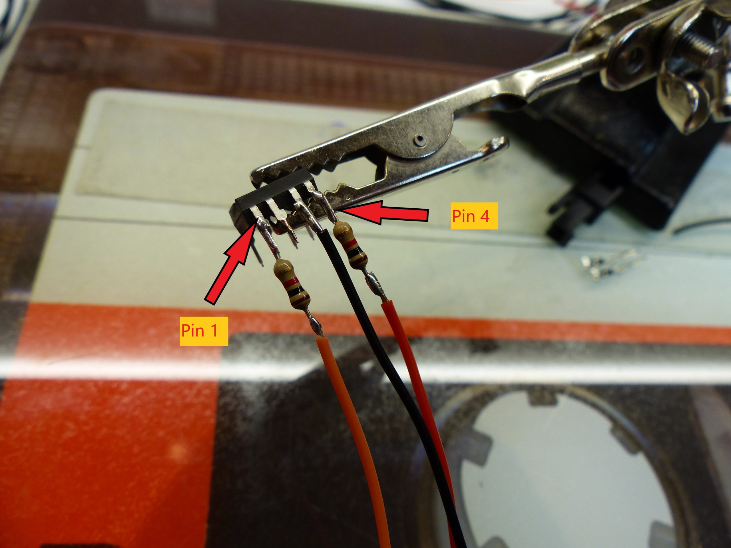
Solder the 1k resistors to Pin 1 and Pin 4. Pin 1 is identified by a notch or dot on the top of the package. With the notch or dot on the left, Pin 1 is on your bottom left.
The Orange wire with crimped end goes to the end of the resistor on Pin 1
The 400mm Orange wire goes to the end of the resistor on Pin 4, and the 400mm Black wire goes to Pin 3
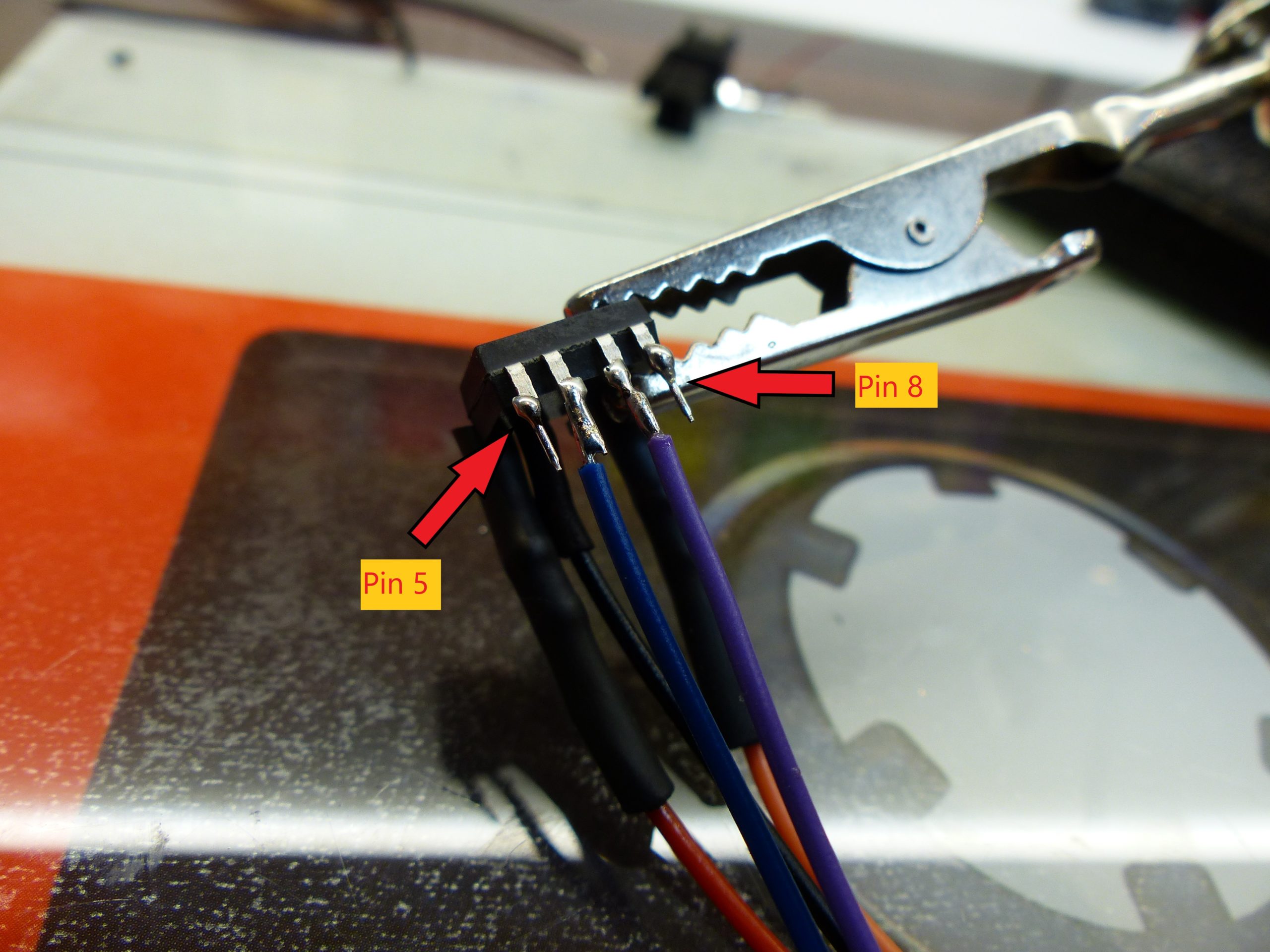
Solder the 70mm Blue wire to Pin 6, and the 70mm Purple to Pin 7.

On the underside, bend Pins 2,5 and 8 in a triangle formation so that they meet together. Then solder the Black 120mm wire across all 3 of these pins, which forms the common ground connection.
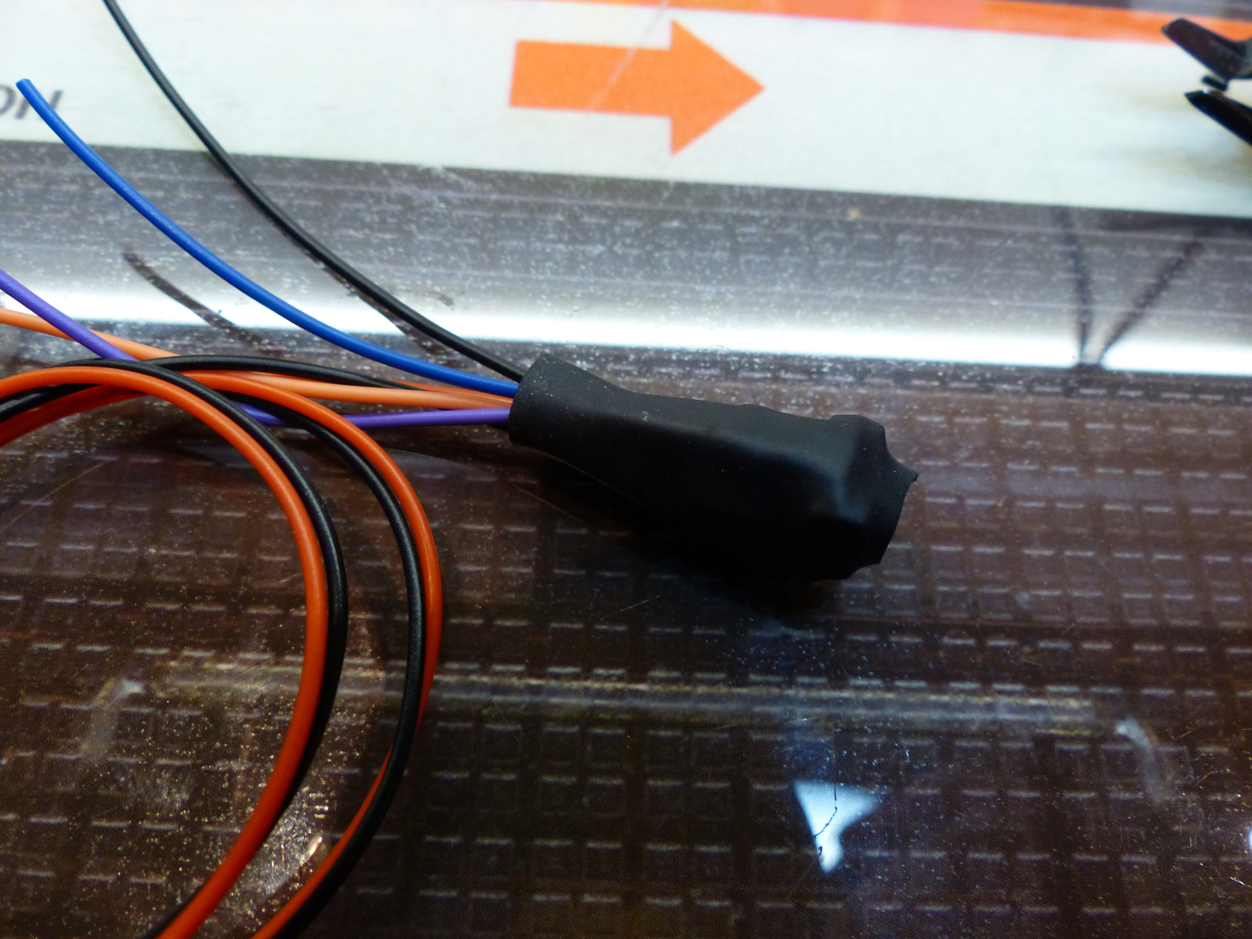
Cover the entire assembly with a length of heatshrink
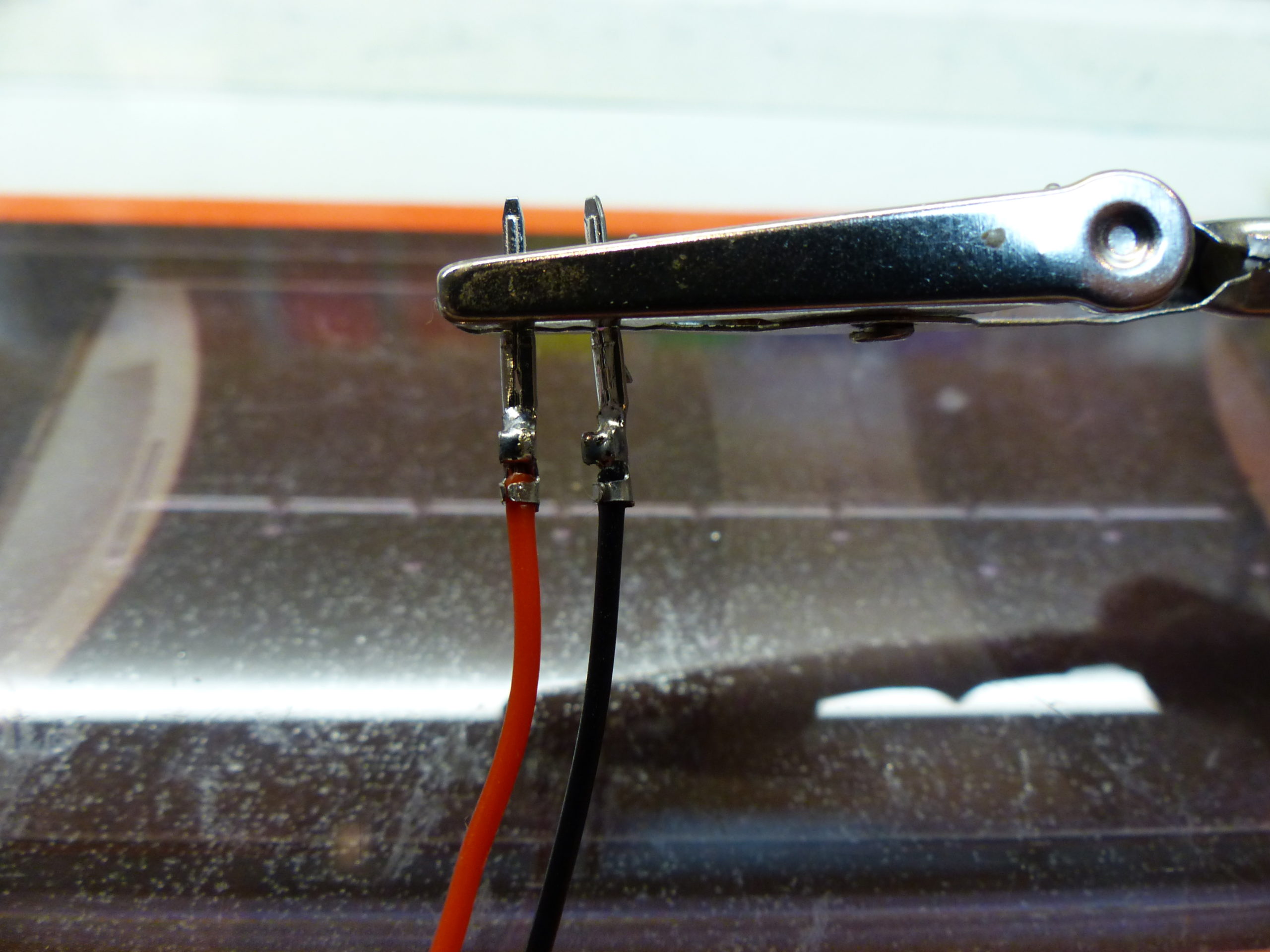
Solder the two pins of connector to the 400mm Orange and Black wires, and insert into the housing
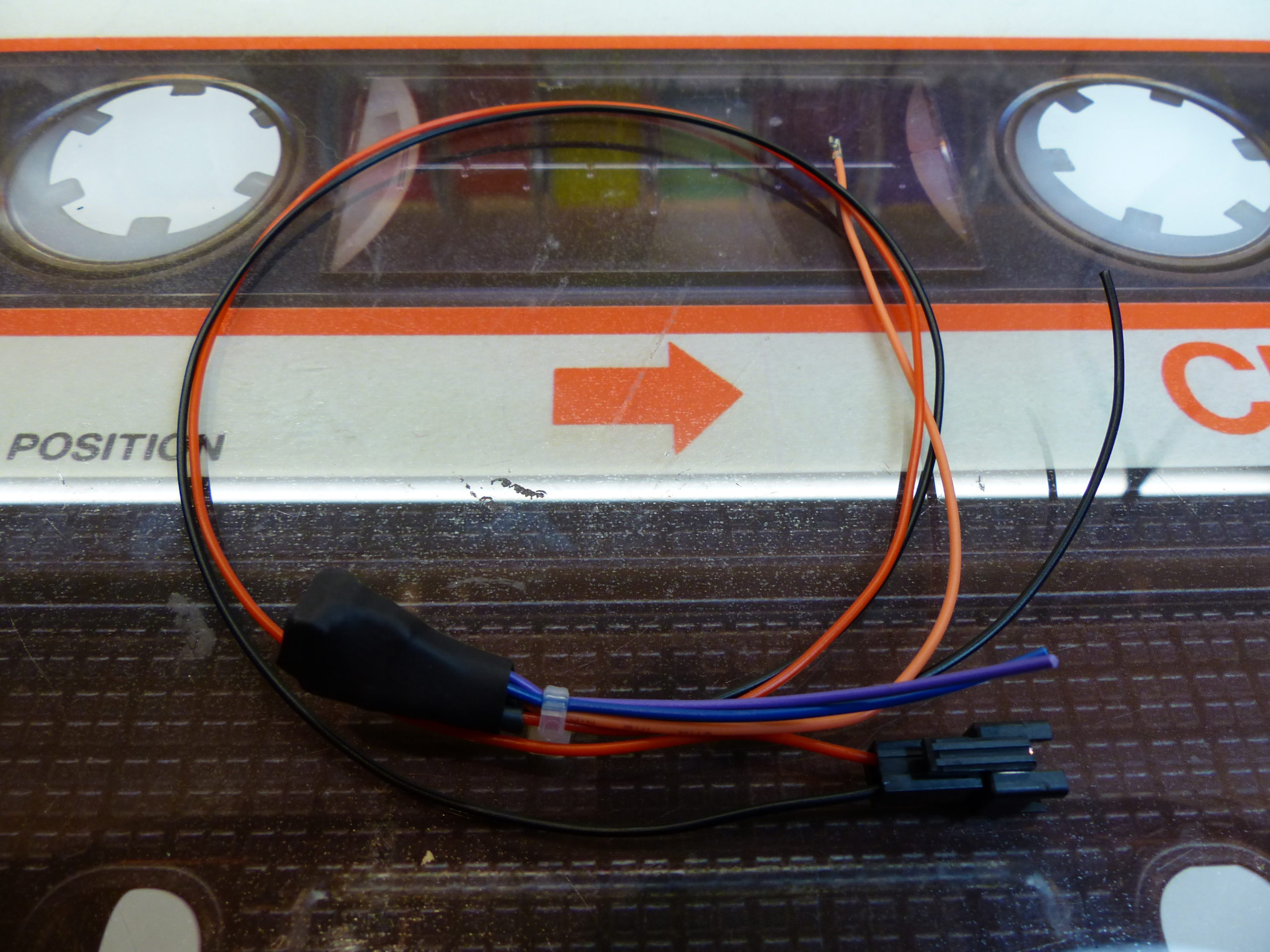
The opto assembly is ready
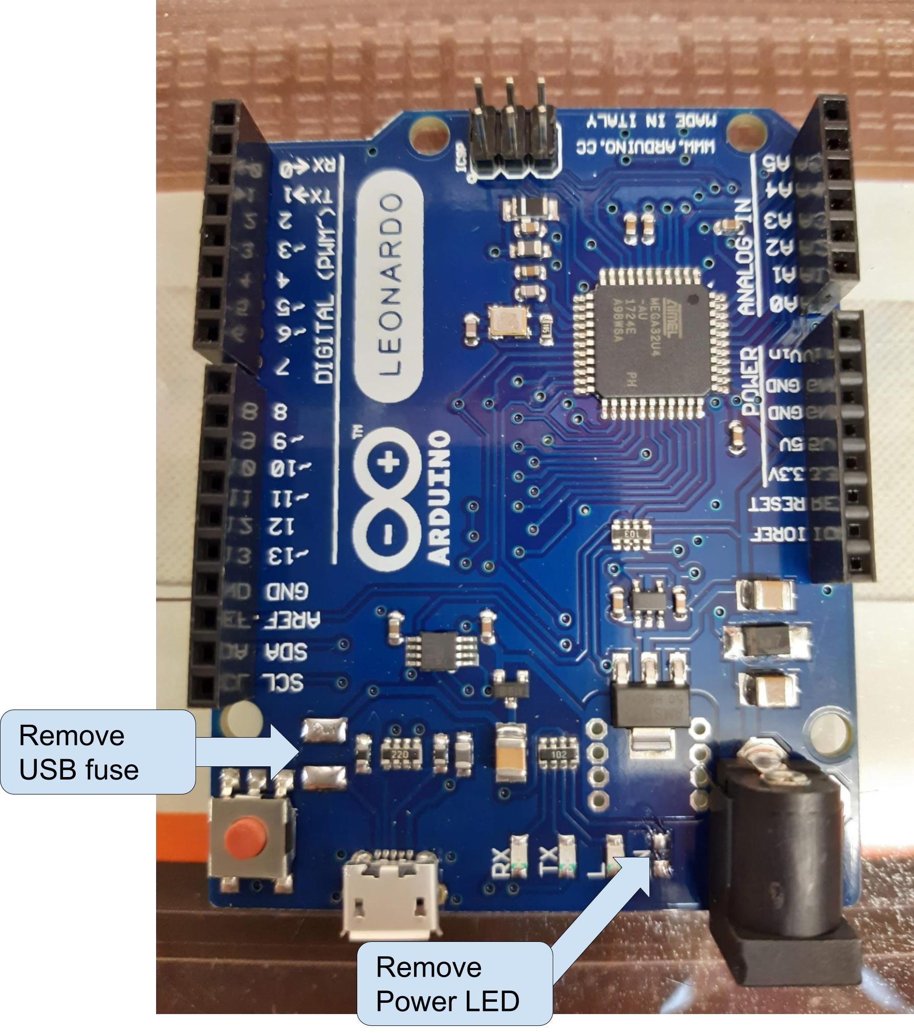
De-solder the power LED and the USB fusable link from the Arduino Leonardo .
Removing the USB fuse prevents the Arduino being powered by the USB connection to the Odroid, when it should only be powered via the head unit power through the voltage regulator.
Removing the power LED lowers the power consumption when the Arduino is in sleep mode.
Continue to the Control board wiring page