
The system uses a RTD2662 based video controller which requires some modification to work in our application.
It needs programming with some custom firmware custom firmware courtesy of the OpenRTD project: http://openrtd2662.ru/ so that it will work with the 15Khz RGBS signal from the original Jaguar DVD-NAV module (which generates the Jaguar graphics screens), and also to allow i2c control of the video input switching so that this can be controlled from the Arduino.
In addition to this there is a small hardware mod to enable dimming of the LCD backlight via a PWM signal from the Arduino, so that the original brightness control in the Jaguar menu will work.
Connections to the i2c bus of the video controller have to be soldered to two pads on a surface mount resistor array which requires a fine soldering iron tip and a steady hand.

This is the type of RTD2662 based video board that you need. There are a few variants of these around commonly available on ebay, Amazon etc, but it needs to look like this one.
The firmware loaded into the controller is specific to the type of LCD panel that will be connected, i.e. resolution and whether it’s TTL or LVDS. You can obtain the correct firmware by contacting the developer at http://openrtd2662.ru/ I use an 800 x 480 resolution panel with TTL (50 pin) interface.
To program the firmware you can follow my YouTube video below, and/or follow the instructions continued underneath:

First of all you will need programming hardware as described here: http://tech.mattmillman.com/info/lcd/rovatools/ftdi-ft232h/, which is an Adafruit FT232H board plus 2 resistors and a 15 pin VGA male connector (the RTD board is programmed via the VGA connector).
Then download the ‘RovaTool‘ program at the bottom of the page here: http://tech.mattmillman.com/info/lcd/rovatools/
The OpenRTD firmware you need if using an 800×480 TTL LCD panel can be downloaded by clicking here
Connect the FT232H programmer to the USB port of your computer and the VGA of the RTD board, then select ‘Open Bank 0’ in the ROVATool, and choose the .bin file. Press ‘Program target’ and then after a few seconds your new firmware should be uploaded to the board!
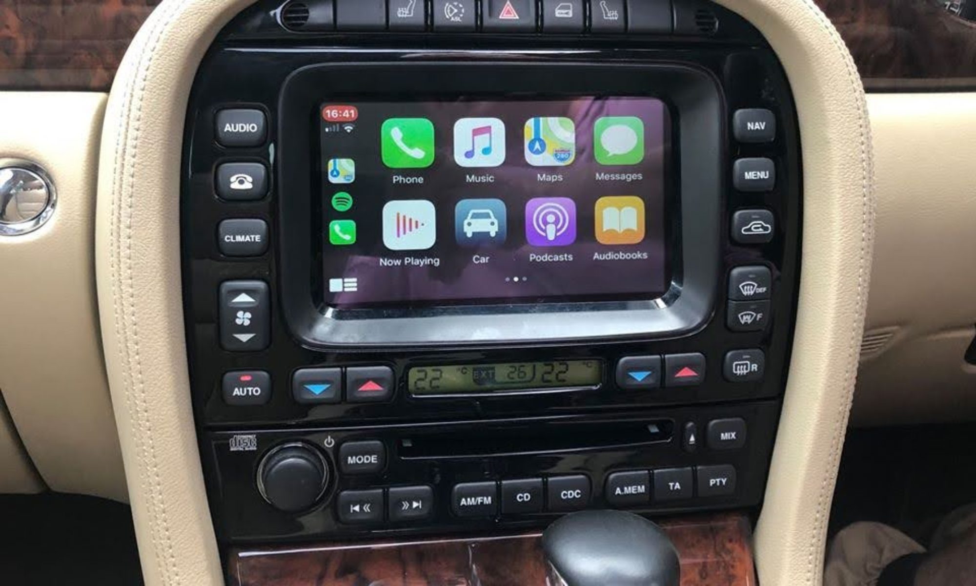
Now you need to perform a small hardware modification to enable PWM dimming on the video board:
Remove the beige coloured 4 pin connector from the corner of the board. Do this by alternating your soldering iron between two of the pins on one side while pulling it up from the board until it lifts away, then repeat on the other side.

Just above the connector that has been removed there is a track going to the bottom right pin of the 6 pin IC. Cut the track going to this pin using a Stanley knife blade
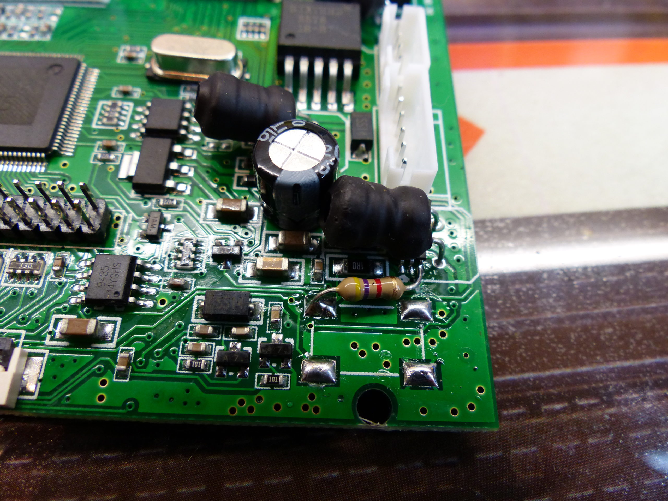
Add a 4K7 Ohm resistor from the top left pad of the connector to the bottom left pin of the IC where we previously cut the track
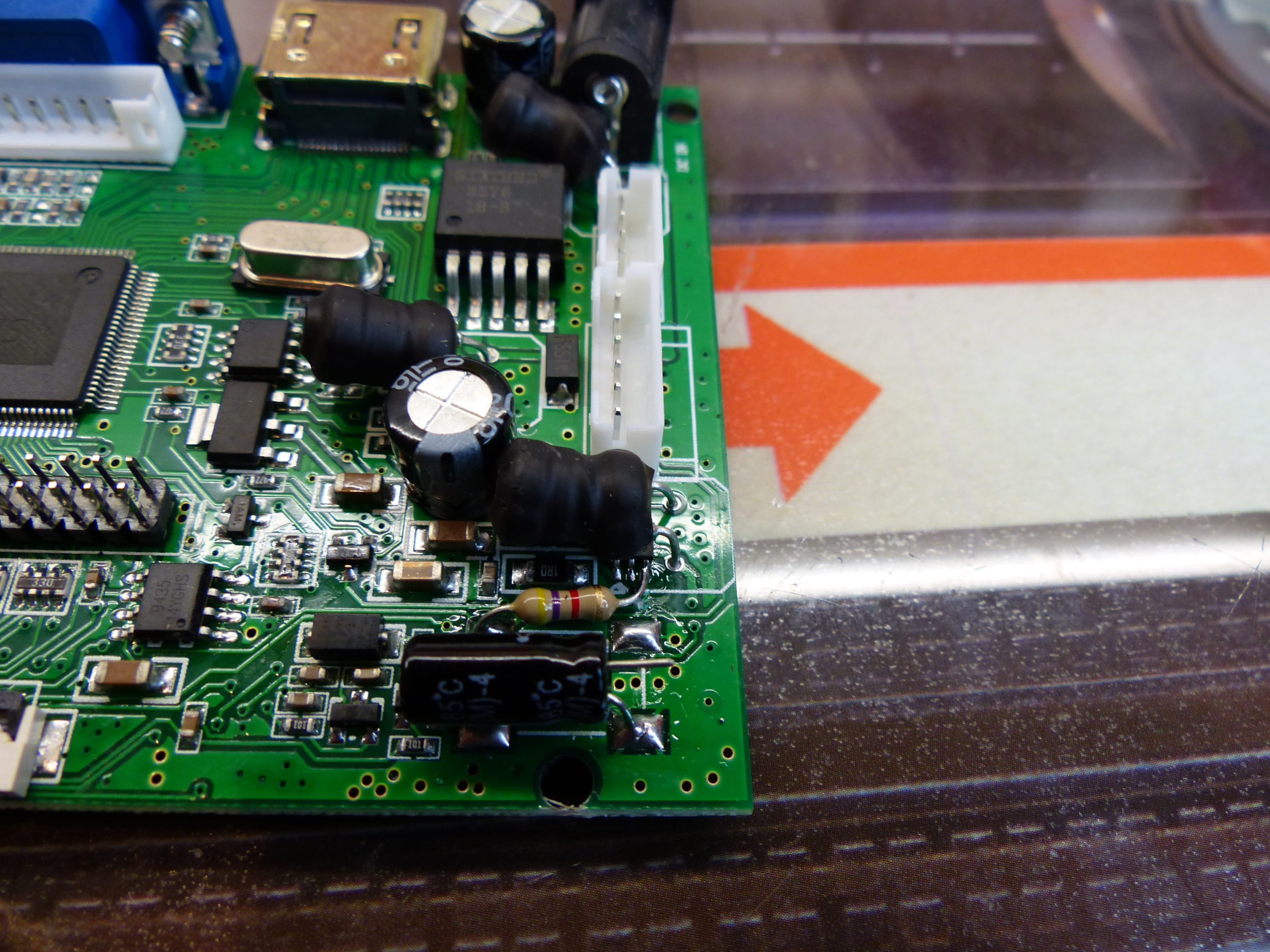
Solder a 10uF 16v capacitor with the -ve lead to the bottom right pad of the connector, and leave about 5mm of the other leg straight out as shown.
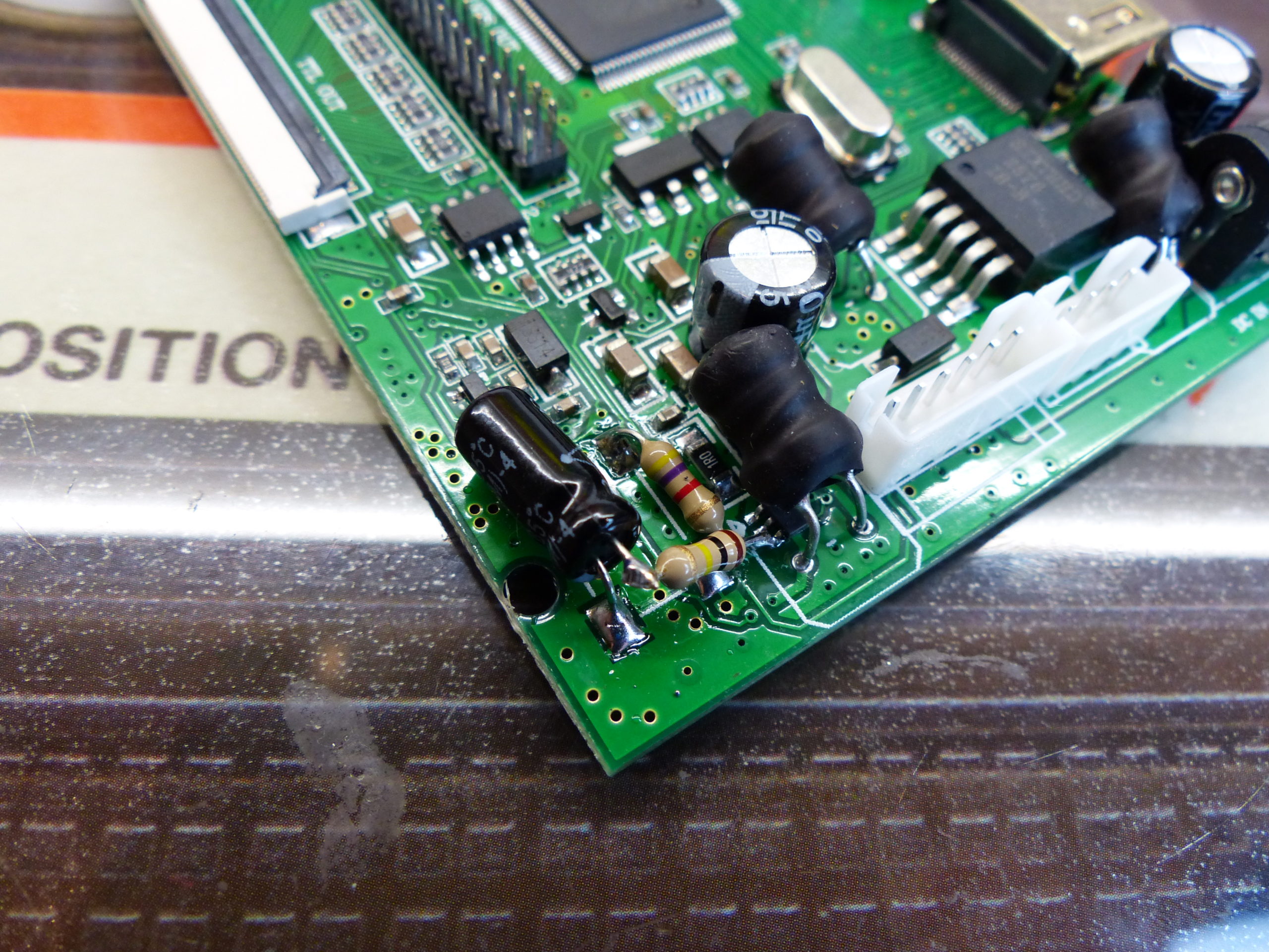
Add a 100k Ohm resistor from the +ve leg of the capacitor to the right-hand leg of the 4K7 resistor

Finally add a 10k Ohm resistor to the +ve leg of the capacitor. The other end of this resistor is the PWM input from the Arduino that will control the LCD backlight brightness.
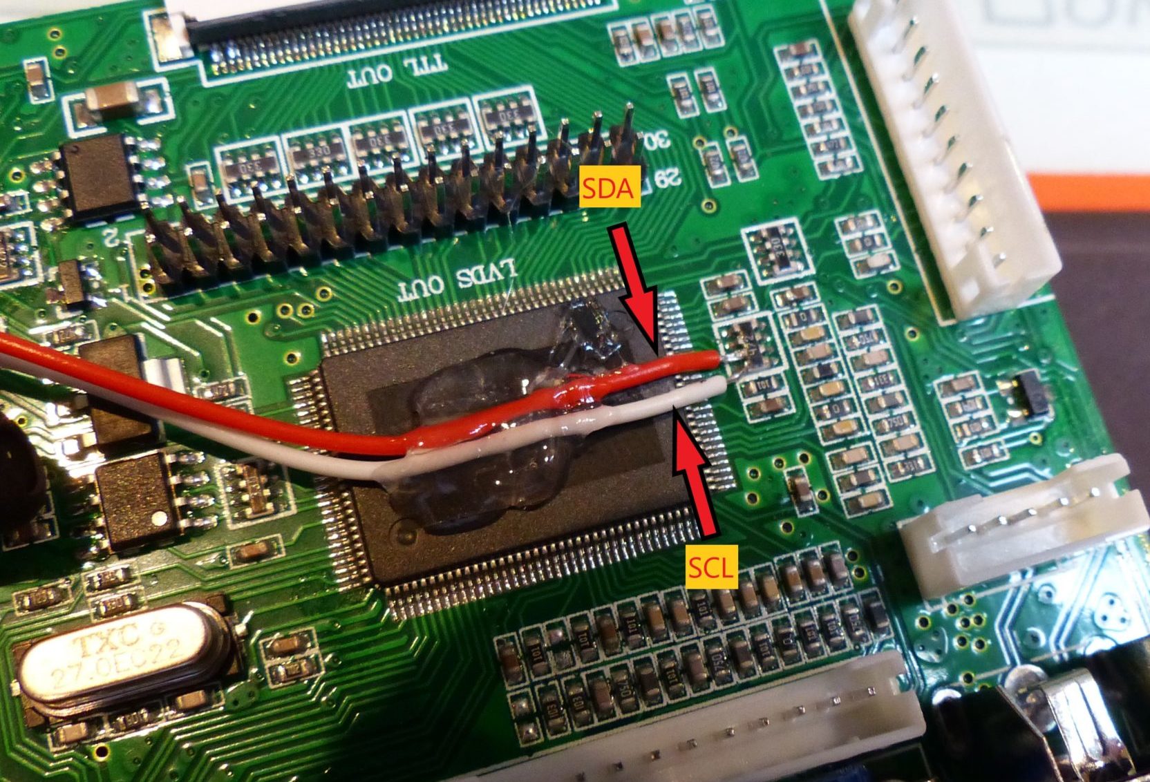
Solder 170mm red and white wires as shown, which are the SDA/SDL connections to the i2c bus. These will be later soldered to the Arduino which is used to send commands to change video input for switching between Jag and Android mode.
Secure to the RTD2662 IC with a blob of hot-melt glue.
Continue on to the Arduino and opto page